Category Archives: Equipment
So I spent my disposable part of the day building an RF Sampler and looking at the oscilloscope. At first I kinda got worried. I saw the image below.
So then I realized that at 20mV per division (you can’t see the pointer in the image, but it IS on 20 mV), that’s not so terrible. Especially when I look at the video below:
This was on 1V per division. So that looks okay I guess. Initially I was concerned about the distortion I was hearing on my wideband HT, but since my HT was on AM (no SSB modes available), it is probably okay.
So I’m on to looking at the antenna and feedline. Next up to build: a field strength meter.
-73-
Last March, I purchased an Icom IC-706mk2g. Since I didn’t have a power supply (and modifying my old Ten-Tec power supply is a project that is taking too long), it sat. For too long for my liking. So I put it in my truck, temporarily, to make sure it works. I had some good comments about the sound quality.
During my afternoon drive, however, I hit a few particularly nasty bumps in the road and the rig, which I had sitting on the transmission hump, slid to the side, pulling on the power and antenna connectors. After that, the comments about the sound quality dwindled to it “sounding staticy, like you’re off frequency”. I took the covers off, did some quick visual checks and didn’t see anything amiss, so I kinda passed it off.
Fast forward a few very busy months with the HF rig off, and to this past week where the 13 Colonies were on the air. Try as I might, I had a lot of trouble getting any of them. In fact, there were times I stuck it out through a pileup (trying every time they said “QRZed?”) to when they were asking “QRZed” twice and even calling CQ. I was calling out, but they weren’t hearing me.
After being heartwarmed by hearing one of the stations clear a frequency to allow a mobile station through, I thought I’d operate mobile. So I attached an antenna mount and a 20m mobile antenna to my truck. The next morning wasn’t particularly good on 20. In the afternoon, I tried hitting up the local repeater first (it had been dead in the morning, and I do like talking with my repeater friends). However, I couldn’t get through. So I tried again in a few miles. And again, a few miles after that. Finally, I could get through when I was pretty close to home. The return ID was staticy, too.
So anyway, I’m concerned for my HF rig.
-73-
I was one of the first among the ham community to get a Raspberry Pi. Since getting it, I’ve felt somewhat lame because it took me a few days before plugging it into my TV and making sure it works. When I did that, I only ssh-ed into it for a few minutes.
I spent the next few weeks trying to figure out what to do. After all, the possibilities are endless. After much thought, I decided the best thing would be some sort of box that would connect to a TV and show something radio related. I thought about it and decided that the screen format of Sports Center (on ESPN) would likely be the way to go. Since it is sports and they try to cover a lot, they have a vertical scrolling bar on the left side that shows what they are talking about next (so you know if you want to stay watching or go to the loo or get another beer). I think that the vertical scroller is something to adapt to this, although it may not be as live as SC, it will give an indication of what’s coming up next.
So for things on that bar, I can think of a few things:
- DX Spots
- Solar Weather
- Contest Calendar or contest stats (when in a contest)
- Log stats (recent QSO locations)
- APRS-IS
- Nearby satellites
Recent Headlines (perhaps from ARRL) (perhaps as a crawler at the bottom of the screen? Perhaps also including other news sources like SARC?)

So I’m looking for both ideas and volunteers. This project will be open-source and emphasis will be on making it skinnable, extendable, and something useful to the ham community. If you have an idea or can volunteer, feel free to leave it in the comments below or email me at callsign at callsign.us.
-73-
I was going to post this to twitter, but it’ll be longer than 140 characters, so I thought I’d put it here.
With Yaesu having began to advertise their C4FM and hopefully demoing it at Dayton in 5 weeks (from this post), and Icom having now 21,900 “registered users” worldwide (note that registered users ≠actual users, as I’ve heard via a twitter/D-Star user that people can register without actually owning any D-Star equipment).
Kenwood, based on their recent QST ads, appear to be ready to unleash another HF rig on us. No telling what their plans are, but they could single-handedly destroy D-Star or C4FM by going with the competing technology. They could also exacerbate the status quo by bringing out their own digital voice/data technology.
Of course, Kenwood probably doesn’t want to get in between Icom and Yaesu by siding with one of them. And I’m not sure if Kenwood wants to add another proprietary-feeling digital mode. They may just be waiting this one out for a winner.
Or maybe we’ll get lucky and Kenwood will figure out a way to build radios with FM, D-Star, and C4FM. 🙂
-73-
Now that I’m done cussin’ at the software (which was doing what it was supposed to, I just didn’t realize that), I have some time to reflect.
First off, 15 and 20 meters were awesome. 10 meters stunk for me – lots of calling from CA, but nobody was hearing my 25 watts from Ohio. 40 meters looked good as well. More on that in a second.
I netted 960 points in 40 QSOs. Two new DX – Cuba and the UK. One #WATwitter – @VA5LF.
I started on 20 and got several. Went to 10 (I think I got one Q there), went to 15 and tore it up. Back to 20, found a few new. Jumped to 40. On my 3rd QSO on 40 my rig quit. Just quit. I thought it had folded back (like it had high SWR). So I turned the rig off and back on. The rig lit up for a split second before dying again. Tried it again, same result. Again. Again. Put my hand on the heat sink on the back. I did NOT yell “ouch!” (or anything of the sort). It was warm, but not hot. Did the same to the power supply, and the same result. I unplugged everything and took the rig over to the bench and removed the covers. Nothing looked burned or bad, but I couldn’t see in the finals. Figuring that’s where the problem would be, I uncovered the finals. Nothing.
So I replaced the bottom cover and moved the rig aside and got the power supply. I tried to pull a pass transistor off the back, but after trying to pry it off with a knife I realized it was soldered on. So I replaced the screws on the pass transistor and plugged it back in to try and put a load on it. After plugging it in at the bench and turning it on, the transistor that I was trying to pry popped from the location I tried to pry it from.
So at least I know I have a bad pass transistor. Maybe two. The rig condition is unknown. I’m going to get a battery and hook the rig to it and see if the rig runs. I honestly don’t want to hook my Astron PS to it, as I don’t want it to blow if there is something wrong with the rig.
-73-
I recently purchased a Heil headset for my old Ten-Tec Omni C. For those that have one, you already know they don’t come with a PTT switch! I’m too cheap and broke to buy one of the nice Heil ones (to go with my used Proset Micro Dual) (not that I think the Heil ones are overpriced – they’re $26 in the latest ham store catalog I received).
So I found a piece of scrap 2×4 and had an extra momentary switch lying around. Sounds like a PTT footswitch to me!
The first part was to drill a few holes – one for the switch and one for the wire out back.
Note: in the second picture, there are two additional holes. Those are from nails or screws in this scrap 2×4’s past life. You can ignore those.
The next part was to feed the wires through. I used a piece of #14 wire to help with this.
Next, obviously was to solder the switch.
Finally, the wires were gently fed back through the hole, tested for continuity (open while the switch was not pressed, and shorted when the switch was pressed) and quickly tested with the radio into a dummy load.
That’s it! Granted, it doesn’t look as polished as some of the manufactured models out there, but since I don’t feel like dropping $26 on a nice footswitch right now, this will do.
-73-
Not long after moving into my house, my 2-year-old Apple Airport WAP “died”. By “died” I mean that I could not connect wirelessly at random times. So I replaced it with a Linksys… which did the same thing. So I replaced it less than a month later with a Netgear. It seemed to work fine for a while, close to a year, and then it did the same thing. However, over time I ran a few network drops and added a radio room in the basement that included a computer. I found that at times the switch still worked but the wireless was out, but some blue LEDs on top were frozen. So I thought the radio was flaky. I went and bought a Linksys WRT-54G, a WAP/Router that I thought would be absolutely bulletproof (and is known throughout the amateur radio community to be a great product). I even decided to stick it to that Murphy guy and bought the extended warranty from Micro Center.
And the same problem happened again. Similar to the Netgear, network access was fine through a wired connection, but unavailable via Wifi. But this time I noticed that I could get wireless back by changing channels.
Not willing to believe that this WAP was dead, I started looking for patterns. The pattern SEEMED (operative word) like it was a cordless phone. So I jacked up the transmit power from the WAP after loading it with DD-WRT. That seemed to work for all of a few hours.
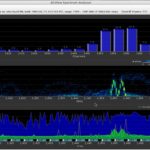
Still with the thought of it being interference from a cordless phone, I took the advice of N8FM via twitter to get a Wifi Spectrum Analyzer. I ordered a Ubiquiti AirView2 spectrum analyzer. After getting it and setting up the software under Fedora Core Linux on my Macbook Pro, this is what I saw:
The first thing I noticed was the clearly-defined frequency range. Not a lot of movement there. The second thing I noticed was the strength. These signals were stronger than the WAP that is 30 feet away on a cabinet in the kitchen with NOTHING between the computer and the WAP. If that’s a cordless phone from my neighbors and still that strong through two exterior walls, I’m not going to have neighbors too long! That would be enough 2.5 GHz radiation to cook their brain – microwaves run at 2.5 GHz!
So I too the computer to an upstairs bedroom and still noticed the strong signals, just not so strong.
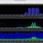
I returned to the family room to let things monitor, and just happened to notice that I have a Samsung soundbar that has a subwoofer with a wireless connection. I immediately ran upstairs, grabbed the laptop, and brought it downstairs and placed it next to the subwoofer. I unplugged the soundbar and subwoofer and the signals were gone! I plugged the subwoofer back in and observed signals running up the spectrum. I plugged in the soundbar and the signals picked a random location to stop at right in the bandwidth for channel 1, right in the WAP’s channel! Clearly the soundbar doesn’t look before transmitting. It also doesn’t have a channel selection switch or a wired subwoofer option. In fact, from observing the signals on the analyzer, it looks like the soundbar starts checking frequencies going down the spectrum, the subwoofer goes up the spectrum, and where they meet, they stay.
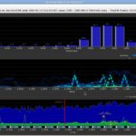
Anyway, after running the spectrum analyzer for a few minutes, it looked like the image below:
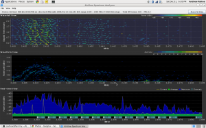
(note that it looked like this after running it for several minutes longer, at least 15 minutes) but the screenshot had a box in the middle of it, so this is what it looks like after a few minutes… they look very similar, which is good).
So the moral of the story is that:
- Samsung soundbar (model HT-WS1G) is junk.
- If you really think your neighbors’ cordless telephone (that you don’t really know they have) is interfering with stuff in your house, you’d do well to go through the troubleshooting steps methodically to avoid looking stupid – I’m glad I never mentioned this to my neighbors because it wasn’t them!
- Any source of interference can be found with diligence and good tools.
-73-
I am working on a Realistic (Radio Shack) HTX-100. I purchased two of these for $45 last May, and was told “one works, one does not”. I joined the HTX-HF_Tech Yahoo group and started looking into things.
The initial problem (but not the ONLY problem) was that there was a lot of static noise from the speaker. This noise was internal to the radio (thanks to a troubleshooting tip I got on Google+ that told me to short the antenna center to shield at the back of the radio).
I started poking around at things, and found that a trimmer resistor was dirty and was causing the static. Combined with the fact that the speaker was desoldered from the board (an oh-so-difficult fix!), I thought maybe I fixed it.
Then I hooked it up to an antenna and checked its ability to receive. Nothing. I could tune stations in on one HTX (and on my Ten-Tec), but not on this one. In fact, I couldn’t tune anything.
One of the things available (not only on the group but also from a few additional websites) is a repair manual, which is really very helpful. I started into the alignment procedure and noticed that in step 3, I was nowhere near the target value of 10.695 Mhz, and was not able to adjust to get anywhere close. So I started looking at the troubleshooting section for the PLL board (where the coil in step 3 was located). A few steps in the process, I checked voltages on one of the ICs and found a handful of them off. I started checking further, and questioned a crystal. I replaced the crystal and found no change. So, I started looking at other things. I checked the voltages on other ICs and found a handful of others that are off. I looked at capacitors, and noticed a few that have tears that seem to indicate that they’ve failed. I replaced one that I happen to have, and it fixed one of the voltages on one of the ICs. Progress! I have a few more to do, but I need to order the parts.
-73-
Last summer, a friend brought me an Astron RS-35 Power Supply to repair. It had been involved in a near-lightning-strike experience that fried the loading coil on an antenna, among other things. The problem was that as soon as the supply was switched on, it would blow the fuse. The only thing that was obvious was that something was causing the SCR crowbar circuit to fire and blow the fuse to save the power supply.
I started out by checking the bridge diodes and filter capacitors. All seemed fine. I checked the pass transistors and those were fine. During a last resort, I removed an electrolytic capacitor and replaced it with another of the same value, but less voltage. My hope was that the voltage on the original capacitor was unnecessary, or that I would have enough time to test a few things before it blew.
Of course, it never happens that way. I had about 15 seconds (not enough time) before letting the magic smoke out of the capacitor. So, since I’m not an electrical engineer, I decided to run a few tests on the blown cap. I noticed that there was no physical damage to the capacitor EXCEPT a small hole in the jacket.
So after staring a little at the schematic (there is an awesome resource on the Repeater Builder website), I decided to remove a capacitor (C6 on the schematic image below). It seemed like a likely possibility, since this was part of the SCR firing circuit (the part I circled in orange highlighter).
Low and behold, it was it! I replaced the part with a new one, and the power supply is done!
-73-
It seems to me the way things are, the ways to run digital soundcard-based modes involves either a new rig and a new (enough) computer with a USB port. Or, you need an old computer with a serial port to trigger the push-to-talk (PTT).
My problem is that I have a MacBook Pro (no serial port) and an HTX-100 (no computer connectivity whatsoever and no VOX). While I can easily connect the mic and speaker to the computer, switching the PTT requires something to get a signal via USB (that something can read) and activate the PTT.
I did this via an Arduino Uno and a transistor and a rig.xml file. It was actually pretty simple, although I did have a little bit of trial-and-error with the rig.xml file.
In fldigi
The first thing to do is setup fldigi to communicate with the rig. This is done by putting the rig.xml file (Arduino.xml) in a good location, such as ~/.fldigi. The XML should look like below:
<!--
	Rig definition file for use with fldigi
-->

<RIGDEF>

<RIG>Arduino</RIG>

<PROGRAMMER>
	Andrew Rohne	AC8JO
	Tested by:		AC8JO
</PROGRAMMER>

<STATUS>
	Tested
	Version:	1.00
	Date:		1 Sept 2011
</STATUS>

<TITLE>RigCAT - Arduino</TITLE>

<!--
default settings for initial setup
-->

<TIMEOUT>0</TIMEOUT>
<RETRIES>2</RETRIES>
<WRITE_DELAY>0</WRITE_DELAY>
<BAUDRATE>19200</BAUDRATE>
<STOPBITS>1</STOPBITS>
<DTRPLUS>false</DTRPLUS>
<RTSPLUS>false</RTSPLUS>
<DTRPTT>false</DTRPTT>
<RTSPTT>false</RTSPTT>
<RTSCTS>false</RTSCTS>
<ECHO>false</ECHO>
<CMDPTT>true</CMDPTT>

<COMMAND>
	<SYMBOL>PTTON</SYMBOL>
	<SIZE>8</SIZE>
	<BYTES>FE</BYTES>
</COMMAND>

<COMMAND>
	<SYMBOL>PTTOFF</SYMBOL>
	<SIZE>8</SIZE>
	<BYTES>FD</BYTES>
</COMMAND>

</RIGDEF>
In fldigi, the setup in Configure – Rig control should be like below, but make sure the device is the correct address for the Arduino Uno. It will be the same address you use to upload the program to the Arduino.
Then, program the Arduino. The sketch is really simple as all it does is respond to the correct string from the serial input and turn on the LED and send some voltage to the transistor base. That allows current to go through the transistor and complete the circuit for the PTT switch. Basically, the transistor acts as a solid-state relay.
The Arduino sketch:
/*
Arduino PTT Rig Interface
Andrew Rohne, AC8JO
1Sep2011
*/

int LedPort=2;
int pttPort=3;

void setup(){
  Serial.begin(19200);
  pinMode(LedPort,OUTPUT);
  pinMode(pttPort,OUTPUT);
  digitalWrite(LedPort,HIGH);
  delay(100);
  digitalWrite(LedPort,LOW);
  delay(100);
  digitalWrite(LedPort,HIGH);
  delay(100);
  digitalWrite(LedPort,LOW);
  delay(500);
  digitalWrite(LedPort,HIGH);
  delay(100);
  digitalWrite(LedPort,LOW);
  delay(100);
  digitalWrite(LedPort,HIGH);
  delay(100);
  digitalWrite(LedPort,LOW);
  delay(500);
}

void loop(){
  String tmp=Serial.read();
  if(tmp=="254"){
    digitalWrite(LedPort,HIGH);
    digitalWrite(pttPort,HIGH);
  }else if(tmp=="253"){
    digitalWrite(LedPort,LOW);
    digitalWrite(pttPort,LOW);
  }
}
As you can see from the sketch, most of the lines are to blink the LED (and this could be done with much fewer lines with two for loops).
The connection diagram is below. Obviously, I had to make a custom cable to go from the 8-pin round connector on my rig to the computer’s mic and phone jacks and the Arduino breadboard (well, breadboard for now).
The above works for me. I will be using it a lot and improving on it, but of you have any improvements, feel free to drop them in the comments.
UPDATE
The new version of Arduino (1.0) doesn’t wants line 33 of the sketch to be the following:
String tmp=(char*)Serial.read();
-73-


