With all the issues surrounding FTDI chips and drivers, I decided I’d look at a competing chip – the Microchip MCP2221. Unlike the “standard” FTDI FT232 (which is most similar to the MCP2200), the MCP2221 includes both a UART and an I2C interface.
Hookup and Configuration
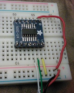
Hooking up this is pretty easy. I sacrificed a USB cable and pulled the red to Vcc on pin 1, black to ground on pin 14, white to Data- on pin 12, and green to Data+ on pin 13.
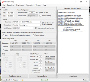
After that, I checked things using the Microchip MCP2221 Utility from Microchip. One of the more interesting things in the utility was being able to configure four pins:
GP0 (pin 2), default is UART RX LED, but can also be SSPND (suspend?) or GPIO
GP1 (pin 3), default is UART TX LED, but can also be CLK_OUT (clock out?), ADC1, IOC, or GPIO
GP2 (pin7), default is USBCFG, but can also be ADC2, DAC1, or GPIO
GP3 (pin 8), default is I2C LED, but can also be ADC3, DAC2, or GPIO
I2C Connection
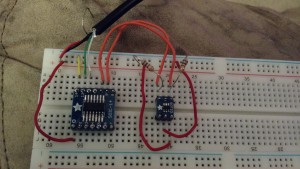
The real reason I got this was to be able to interface to both I2C devices and UART (serial) devices, so I hooked a TC74 temperature sensor to it.
The hookup is straightforward, the TC74 uses four of it’s five pins, Vcc, ground, SCL, and SDA. Vcc and ground are pretty self explanatory, SCL and SDA go to pins 10 and 9 on the MCP2221 (respectively). The SCL and SDA lines need pull-ups, I used 1.5k resistors.
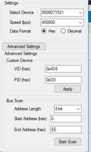
To check things, Microchip provides an I2C/SMBus Terminal program.
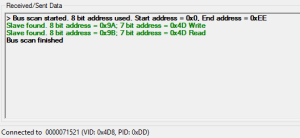
Under “Advanced settings” you can scan the bus by giving it a range to scan…
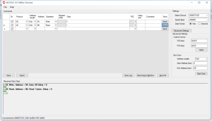
Once I verified that the sensor was where I thought it was, I used the terminal tool to read it…
So the next steps are to figure out what I want to do with all this… I’m partly thinking a multi-function breakout board – UART, ADC and DAC
-73-

