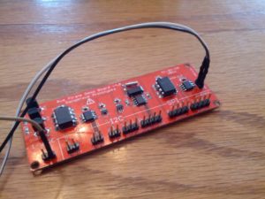
In learning how to use the Bus Pirate, I started with the one-wire area of the demo board.
First off, important notes:
- I’m using the v 3.8 Bus Pirate. The pinout is different than some of the others.
- I’m using a Sparkfun Bus Pirate cable.
My cable is as follows:
Black: Ground
White: 5V
Grey: 3V3
Purple:VPU
Blue: ADC
Green: AUX
Yellow: CS
Orange: MISO
Red: CLK
Brown: MOSI
The first part of this is based on using the DS2431 1,024 bit (1 kilobit?) EEPROM. The second part is using the DS1822 temperature sensor.
1K EEPROM
I used the instructions on Dangerous Prototypes as a guide.
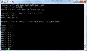
I hooked the ground (black) to the ground, the 5V (white) to Vin (the 3.3-5V pin), and MOSI (brown) to One Wire. Then, open the bus pirate and get into one-wire mode (m {enter} 2) and turn on the power (W). Then, issue the search macro ( (240) ).
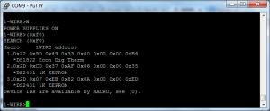
Use (240) or (0xf0) to search the one-wire bus. The bus pirate will return a list of all items on the bus. In my case, I have two EEPROMs (thanks to not being able to get a part) and a temperature sensor.
Writing to the EEPROM to a Temporary Location
To write some values to the EEPROM, I used the following:
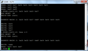
(0x55) (2) 0x0f 0 0 8 7 6 5 4 3 2 1
(0x55) is the macro to ‘match 64 bit address’
(2) is the macro to the address of the EEPROM I’m writing to
0x0f is the command to write to the devices scratch pad
0 0 is the location to write to
8 7 6 5 4 3 2 1 is the data that I’m writing
Reading (Verifying) What I Wrote
To read the string of numbers, I used the following
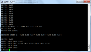
(0x55) (2) 0xaa r:3 r:8 r:2 r:2
The first two are similar to above – (0x55) to match the address and (2) for the macro to the address I wrote to.
0xaa is the read scratch pad command
r:3 reads the authorization code (needed to permanently write the data)
r:8 reads the data I wrote in the last step
r:2 reads the CRC
r:2 this is all ‘1’s
The final r2 returns 0xFF, which is 2 bytes of 1s, in decimal this is ‘11111111’ ‘11111111’.
Permanently Writing the Data
To permanently (well, permanent until I rewrite it) write the data to the EEPROM, I used the following:
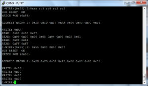
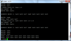
(0x55) (2) 0x55 0x00 0x00 0x07
(0x55) (2) is the same as above
0x55 is the command to write the scratch pad to memory
0x00 0x00 0x07 is the authorization code from above
Verifying the Write
To verify the write, I used the following:
(0x55) (2) 0xaa r:3
(0x55) (2) is the same as above
0xaa is the read command (same as above)
r:3 means read three bytes. The data that is returned is 0x00 0x00 0x87, which is different from before
Reading Back the Data
To read the data, I used:
(0x55) (2) 0xf0 0x00 0x00 r:8 r:8
(0x55) (2) is the same as above
0xf0 is the read command, but this is read from the memory, not the scratch pad
0x00 0x00 is the address
r:8 r:8 reads 8 bytes, twice
The first string returned is 0x08 0x07 0x06 0x05 0x04 0x03 0x02 0x01, which is the data we wrote. The next string is 0x00 0x00 0x00 0x00 0x00 0x00 0x00 0x00, which is data that was never written, so it is all zeros.
That’s it! I read and wrote to a small EEPROM. If it isn’t obvious from the picture above, this is about the same size as a small BJT transistor.
Reading from a DS1822 Temperature Sensor
The DS1822 is a one-wire temperature sensor that is also the size of a BJT transistor. Reading from it is pretty easy and was described on Hack-A-Day by Ian back in 2008.
This is in the same setup as above, so looking in the screenshots above, the proper address for this device is (1).
To read from the device, two commands must be entered:
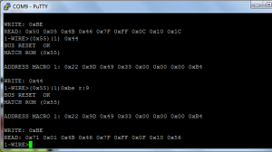
(0x55)(1) 0x44
(0x55)(1) 0xbe r:9
The first command is a “Convert temperature” command, which basically tells the sensor to read the temperature.
The second command reads 9 bytes from the sensor. The important part are the first two bytes. In the example above, the first two bytes are 0x71 0x01. This translates into being read as 0x171 (see note). That 0x171 needs to be converted into decimal, in this case 369. That number then needs to be multiplied by the resolution, which if never changed is 0.0625. That comes out to a temperature of 23.06C, or 73.5F.
-…-
This is the first of a multi-part series. Next installment in this series (hopefully next week) will be the I2C bus, although depending on the length (there are several chips there), it may be broken into two parts.
-73-

