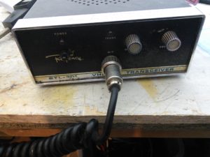
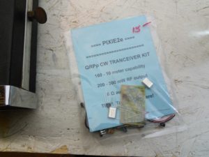
As what was on twitter last week, I took a vacation day on Friday and went up to the Hamvention. I didn’t buy much, just a small kit and a rockbound 6m FM rig. The radio was $5 (it makes it feel so much better to mention the price when talking about the fact that it is rockbound).
The first thing I looked into was the 6m rig. I plugged it into the power supply and a dummy load with a watt meter and hit the TX… nothing. I even tried yelling and whistling into the microphone (which didn’t – and shouldn’t have – made a difference).
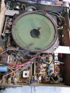
I took a look inside. I figure there is at least $5 worth of parts in here, so it isn’t a loss. Or I could try to fix it, but I’m not sure that would be worth my time.
The better part of Hamvention was meeting several twitter friends in person and catching up with a few local (and non-local) friends that I don’t see often. That definitely made it a good trip!
-73-
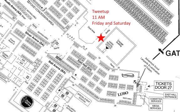
Tweetup: Meet your fellow “tweeps” at Hamvention. 11:00 AM both Friday and Saturday (and Sunday, if anyone wants to meet) at the Hara Arena Loading Dock. This is the same location used for the past two years. Meet near the drayage building to be in the shade (presuming it isn’t raining).
Rain Plans: There is a 40% chance of rain on Friday, and a 30% chance of rain on Saturday. Should it be really raining (not drizzling), we’ll meet in section 30 of the main arena, although that may move.
Frequencies: There will be a talk-in frequency circulating via Twitter via DM. It’ll be somewhere on 70cm.
Direct link to large map (right-click to save, sorry it isn’t a PDF).
-73- and see you there!
I decided a few weeks ago to bring some life into my office with a plant. Since I was getting a few things at the local 24-hour megalowmart, I decided what the heck. One plant, bag of dirt, and pot (that was on sale), I had this…
I decided I wanted something to help me keep this thing alive. I didn’t want to go the route of a twitter reminder, as I’m in here nearly every day. A nice, visual indicator should do well.
Since I’m a traffic engineer, I thought something with a traffic signal would be appropriate. A green for “you’re good”, a yellow for “getting dry”, and a red for “too dry”. I also like the idea of using a PIC since I haven’t used those very much and I wanted to expand my horizons.
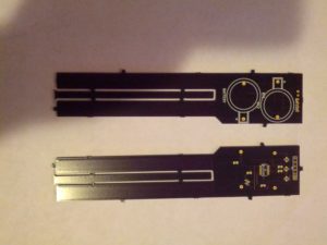
After some breadboard experiments on a breadboard, I even designed my first PC board.
The circuit uses two coin cells, a PIC 16, and a few other components (click for schematic). There is one issue with the boards – there is silkscreen covering the copper that is supposed to sense the moisture in the soil. I’ll have to fix that with a razor.
Stay tuned to see how it does, once I solder components and build. I’ll post the source then.
-73-
Last week (on a post that proved that even an evil genius can sometimes mess up simple math and set a post to fire 4 days early) was the introduction, today is some new findings.
Memory
If you follow the directions and treat this like an “Arduino Pro or Pro Mini (3.3 v, 8 MHz) w/ATMega 328”, the Arduino compiler will tell you that there is a 30,780 byte maximum. In my experience, the maximum is around 26,000 bytes. Wyolum knew about this, and this is why they included a micro-SD card slot and card. At one point, I tried creating a program that would tell the temperature and lines from the Zero Wing intro (“All Your Base Are Belong To Us!”). It didn’t go well.
Temperature Sensing
The temperature sensor is very simple to use. Recall in the last post, the sensor itself is populated, but a 0.1 uF capacitor (C8) is not. The sensor might work without the capacitor, but it likely works better with it (at least I hope so, I populated the cap without testing and I have zero interest in removing it).
To read the analog pin and get it to a voltage, the following code works for me:
int ar=analogRead(7);

float vref=3.3;

float temp=ar*vref/1024.0;
Even though the Pro and Mini do not have 7 analog pins, the Arduino IDE and compiler not only do not complain about not having the pin, they compile it correctly without modifying any of the libraries (Good on ya, Arduino!).
Looking at the data sheet, there is a simple equation for the temperature:
$$V_{out}=T_{C}*T_{A}+V_{0}$$
Where:
$$V_{out}$$ is the output voltage
$$T_{C}$$ is the temperature coefficient
$$T_{A}$$ is the Ambient Temperature
$$V_{0}$$ is the voltage at 0°C
Per the documentation, I used $$V_{0}=0.5v$$ and $$T_{C}=0.01V/°C$$. Using algebra (who says you’ll never need it?), I used:
$$T_{A}=\frac{V_{out}-V_{0}}{T_{C}}$$
Which would give me the temperature in Centigrade, and after that,
$$T_{F}=\frac{9*T_{C}}{5}+32$$
In Arduino, that wen’t like this:
temp=temp-0.5;

temp=temp/0.01;

// C to F

temp=(9*temp)/5+32;
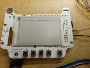
And it seemed to work correctly. I was getting temperature readings of around 74 in my office, and it seems like that is correct. The final code is below.
…and of course, I can’t show all this code without the finished product:
By the time this post fires, I will have just returned from a transportation conference. I hoped initially that I’d have more with this post, but it’ll have to wait for next week’s post.
-73-
Ever since seeing the name badges from the Open Hardware Summit 2013, I wanted one. I tend to make it to 2-4 transportation conferences a year, plus 3-5 hamfests, so having a cool looking badge is… well, just a want.
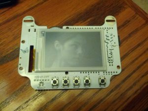
The front. Five buttons and an e-ink screen.
First off, the e-ink screen idea is pretty awesome. It maintains an image with the power off, which is a great feature (especially since there are only around 100 page turns on that coin cell).
The powerplant of this is an Atmega 328p. The same Atmel processor used in the Uno, Pro, Nano, Fio, and some Lilypads.
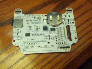
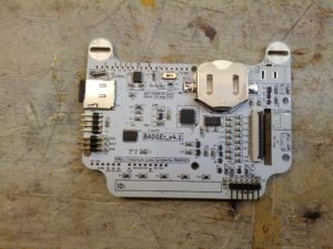
Per the website, there are two unpopulated items – a realtime clock and a temperature sensor. However, looking at the schematic and the board, I see the unpopulated realtime clock area in the upper left area of the board, but in looking just to the left of the 328, there is a temperature sensor – the only unpopulated area is for a 0.1 uF capacitor!
I didn’t even program the thing before fixing those little omissions. I had to make a little change to the realtime clock I had is an NXP, and the doc calls for a TI chip. The only difference – pin #3 is a backup power input on the TI chip, and on the NXP chip it is an interrupt output. I clipped the pin prior to soldering. I also soldered the ICSP and I2C connections, since I think I may end up using those at some point.
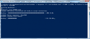
The first thing I did with the BADGEr is get a copy of the firmware that is on it. After trying to use avrdude with an FTDI board, I did what I should have done the first time – used the Bus Pirate. Using the connection instructions on Dangerous Prototypes’ website, I used the following avrdude command:
avrdude -c buspirate -C”..\etc\avrdude.conf” -P COM9 -p m328p -U flash:r:”C:/badgr.bin”:r -b115200
** CASE SENSITIVE **
The -c option tells avrdude what programmer avrdude is using.
The -C option tells avrdude the configuration file. In my case, I’m running this from somewhere down in the Arduino IDE folder, and relatively speaking, backup one and then into the etc folder.
The -P option is the port number (in my case, COM9)
The -p option is the part number, in the case of the BADGEr, it is an ATMega 328p and per this page, that is the correct string to use.
-U is the operation. ‘flash’ is the part of memory to work with, r means to read, the next part is (obviously) the file path, and the final r is for ‘raw binary’.
-b115200 is the connection speed. My Bus Pirate is setup for 115200 bps, so I used this. It will not work if incorrect.
Once I ran this (well, twice because I forgot the final r option in the -U portion), I got a raw file with the code on the device.
It took 1,048 seconds, or about 17.5 minutes. For a 32 KB file. There’s some fixes for that HERE. Use them well.
Initial Programming Experience
After screwing around for several days trying to load the BADGEr from SPI, I fixed one of my FTDI boards and got it to work. My advice here: don’t even mess with trying to load sketches via the SPI interface. It won’t work (and I’m not sure that was ever intended).
Initial Program
Thoughts
The battery included died very quickly. I think my next improvement will be a better battery! This DOES need a good power source when programming. I initially used my Bus Pirate to power it while programming it from the FTDI cable.
-73-
On the heels of NT7S announcing that he’s taking the red pill on Etherkit, I ordered a CRX1. I decided this would be a good chance to try reflow soldering with the solder paste I added on the last Mouser order I placed.
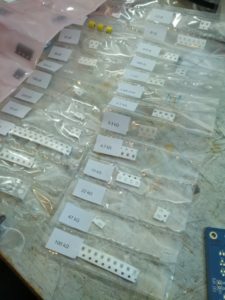
First off, on the kit. This is how things SHOULD be packaged, especially with SMDs.
Onto the build.
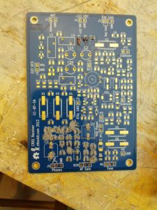
I used the syringe and a screwdriver to spread what was sometimes too much paste on the pads…
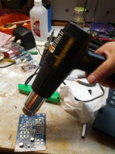
Then heated it up until I saw the components move into place (I have to admit that seeing the components move to the correct place is AWESOME!) and the solder looked fully heated.
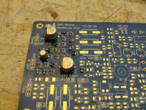
The end result looks like this.
Lesson learned: tools made for removing flooring are NOT meant for electronics! In the pic, the plastic bases for the electrolytics are starting to melt. That can’t be good; hopefully those caps didn’t get too hot. Also, it may have charred my workbench. Hopefully by the time this posts I will have purchased something better (like a real soldering station!).
This is the last of the series of using the Bus Pirate and the Bus Pirate Demo Board. This one is using the SPI EEPROMs. The board has two of the same EEPROM (well, one is SOIC, the other is DIP, but other than that, they’re the same).
Connections
The power connections for this are the same as the connections you’d use for an I2C device – ground and power (I used 3.3V) + pull-up to Vin.
The data connections are pretty simple because the Bus Pirate is marked with MISO, MOSI, CLK, and CS (Master In Slave Out, Master Out Slave In, Clock, and Chip Select) and the demo board is marked with MISO, MOSI, SCK, and CS (there is one difference, and the process of elimination fixes that!).
Writing and Reading to the EEPROM
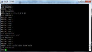
There are two steps to write to the EEPROM – send a write-enable command and then write to it.
[0x06] – write enable command
[0x02 0 0 1 2 3 4 5] – 0x02 is write, 0 0 is the address to write to, and 1 2 3 4 5 is the data to write
[0x03 0 0 r:5] – 0x03 is the read command, 0 0 is the address, and r:5 means read five bits.
—
That’s it with the demo board! Expect that the Bus Pirate will make more appearances on this blog, though.
-73-
This is the second post on the Bus Pirate Demo Board I2C, showing the MCP4725 digital to analog converter and the PCF8563 real-time clock.
Connections
Like the last post, the ground and Vin need to be connected, and VPU (the pull-up resistors) need to be connected to the Vin as well. CLK on the Bus Pirate needs to be connected to SCL, and MOSI on the Bus Pirate needs to be connected to the SDA pin. There are other connections that will be necessary and will be different for each.
Digital to Analog Converter
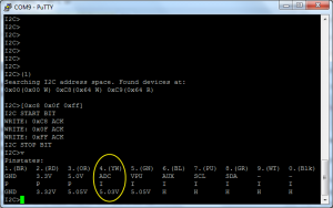
The additional connection that needs to be made for this is the ADC connection on the Bus Pirate should be connected to the OUT pin on the demo board. This will allow you to see the output. As shown in this video by Mike Parks, it is pretty easy to address and use.
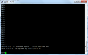
(1) – macro to search for address
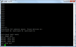
[0xc8 0x0f 0xff] – turn the analog output to full
v – show voltages
Note the ADC voltage, which is at 5.03V (the max it will show).
To change things, try using [0xc8 0x01 0x00]. It will set the voltage to 0.30V. using …0x00 0x00 will turn the ADC to 0V. It is linear from 000 to FFF hex, so 800 (0x08 0x00) is half, and so on.
Real-Time Clock
The RTL uses the same SDA, SCL, and power connections as above, and those are the only necessary connections. However, the ADC and AUX connector CAN be used if wanted.
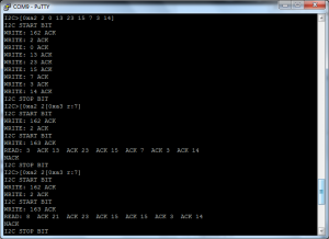
Setting and retrieving the time can be done using the following (ref):
(1) – address search macro
[0xa2 2 0 13 23 15 7 3 14] – 0xa2 is the address, 0 is the location to write, and I’m writing
[0xa2 2 [0xa3 r:7] – 0xa2 is the address, and 2 is the address to READ from in the next command, 0xa3 is the read location, and it reads 7 bits.
It seems to me that connecting the AUX on the Bus Pirate to the CLK pin on the clock should be measurable (by using f in the BP interface), but I’m not seeing a reading, so it may not be the correct way to use that. However, when I took the AUX wire and held it to pin 1 on the RTL IC and read the frequency, it came up to 60 Hz, and was not controlled by sending commands to the 0x0d address.
-73-
Yes, I shouted that. And for very good reason – Arduino started me down the road of playing with micro-controllers (you can tell I haven’t made a red cent on any of this – I call it “playing” :-)). I guess you could consider Arduinos to be my gateway drug into Raspberry Pis, Beaglebones, and PICs.
In celebration of Arduino Day, I decided that I should list a few of my favorite Arduino Projects (some are still in progress).
This is probably the coolest thing I started to write. It is also the most useful, as it would have it’s uses with any receiver setup, whether it is a home-built radio, an RTL-SDR, or even an off-the-shelf radio).
I didn’t do very much with this, and what I really learned wasn’t even discussed in the post- I really learned how to ‘break out’ of the Arduino IDE and load an Arduino from the command line. With Linux.
The Arduino Easy Logger Button
This is the start of what ended up netting me a ChipKit WF32. I want (and still need to finish) a setup that makes it easy to log my radio contacts while mobile. The Arduino version is around 90% done, but with several things taking my time it hasn’t been finished. And the ChipKit version has got a longer road.
-…-
I thought I’d have more of these, but I guess I don’t. I do have a few “in the queue”, though, so hopefully when I write some for AD15, I’ll have a few more. Either way, I’ve learned A LOT and I know I have several more posts coming that use my Mega 2560 and Due (and maybe even that Leonardo I picked up a few weeks ago).
-73-
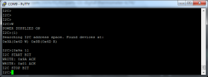
The Bus Pirate Demo Board has five I2C devices: two 24AA02 EEPROMs (2 KBit), one TC74 temperature sensor, one MCP4725 D/A Converter, and one DS1307 Real-Time Clock. This post is about the EEPROMS and the TC74 – next week’s post will be about the D/A converter and the RTC.
Pull-up Resistors & Connections
One thing that is not documented well enough for non-engineers is the pull-up resistors. They are pretty important for I2C devices and results can be weird. What needs to happen is to have BOTH the 5V and pull-up lines to the Vin pin on the demo board. I used a breadboard for now, although I have a different Bus Pirate cable on the way to make this a little easier.
In both the cases in this post, the CLK pin on the Bus Pirate gets connected to the SCL pin on the demo board and the MOSI pin on the Bus Pirate gets connected to the SDA pin on the demo board.
EEPROMs
Both of the EEPROMs are interfaced the same way.
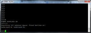
Search for the EEPROM Addresses:
(1) is the address search address
[0xa0 0 3 2 1] – 0xa0 is the address to write to, 0 is the location in that address (the top), and 3, 2, and 1 are the values being written.
[0xa0 0][0xa1 r:3] – 0xa0 is the address, 0 is the location in the address. 0xa1 is the read command, and r:3 indicates to read three bits.
[0xa0 0xfa][0xa1 r:6] – this is to read a MAC address from the chip. Unfortunately, I can only seem to get all F’s from these chips… I’m not sure if I’m doing something incorrect or if the chip’s spec has changed since the instructions on Dangerous Prototypes were written.
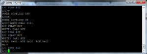
As a final test, I cut the power to the board (w) and turned it back on (W) and read the chip to see if the values were still there. They were.
TC74 Temperature Sensor
The TC74 Temperature Sensor is an interesting device to use.
(1) – standard address search macro
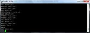
[0x9a 1] – 0x9a is the address, 1 is a value to write. We don’t really care what it writes, we just need to do this to read the chip.
[0x9a 0][0x9b r] = 0x9a is the write address, 0 is a partial command to select the temperature register, and 0x9b r reads the register.
The value returned is 0x16, which is 22°C, or 71.6°F.
…next week – more I2C goodness!
-73-

