
Tag Archives: antenna analyzer
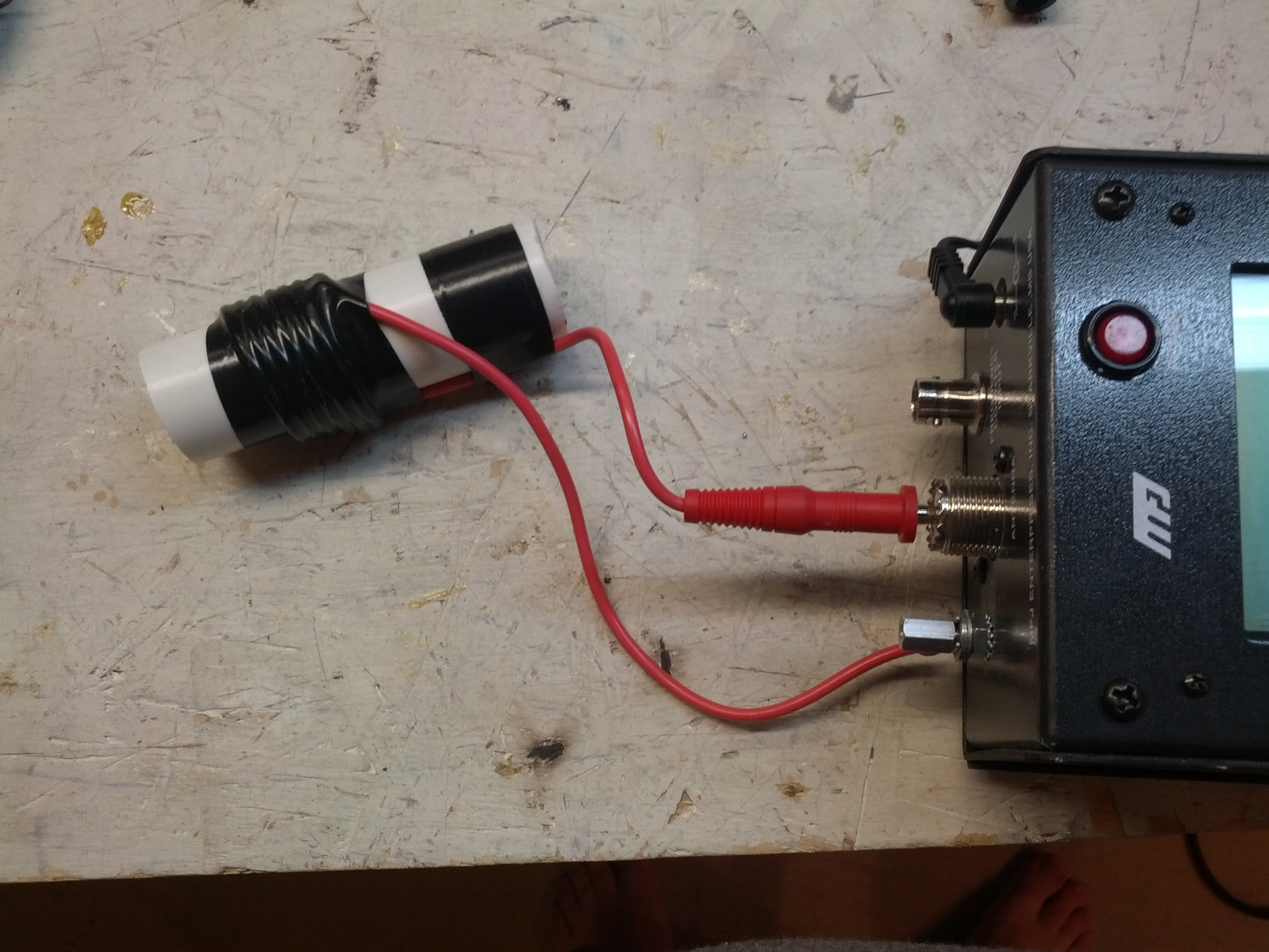
I recently had the need to check a transceiver to ensure that it was on-frequency. This is easiest done with a frequency counter, which is included in an MFJ Antenna Analyzer. I use an inductive coupler made from some coil wire around a small (1/2 inch) piece of CPVC, with the coil connected to a BNC connector.
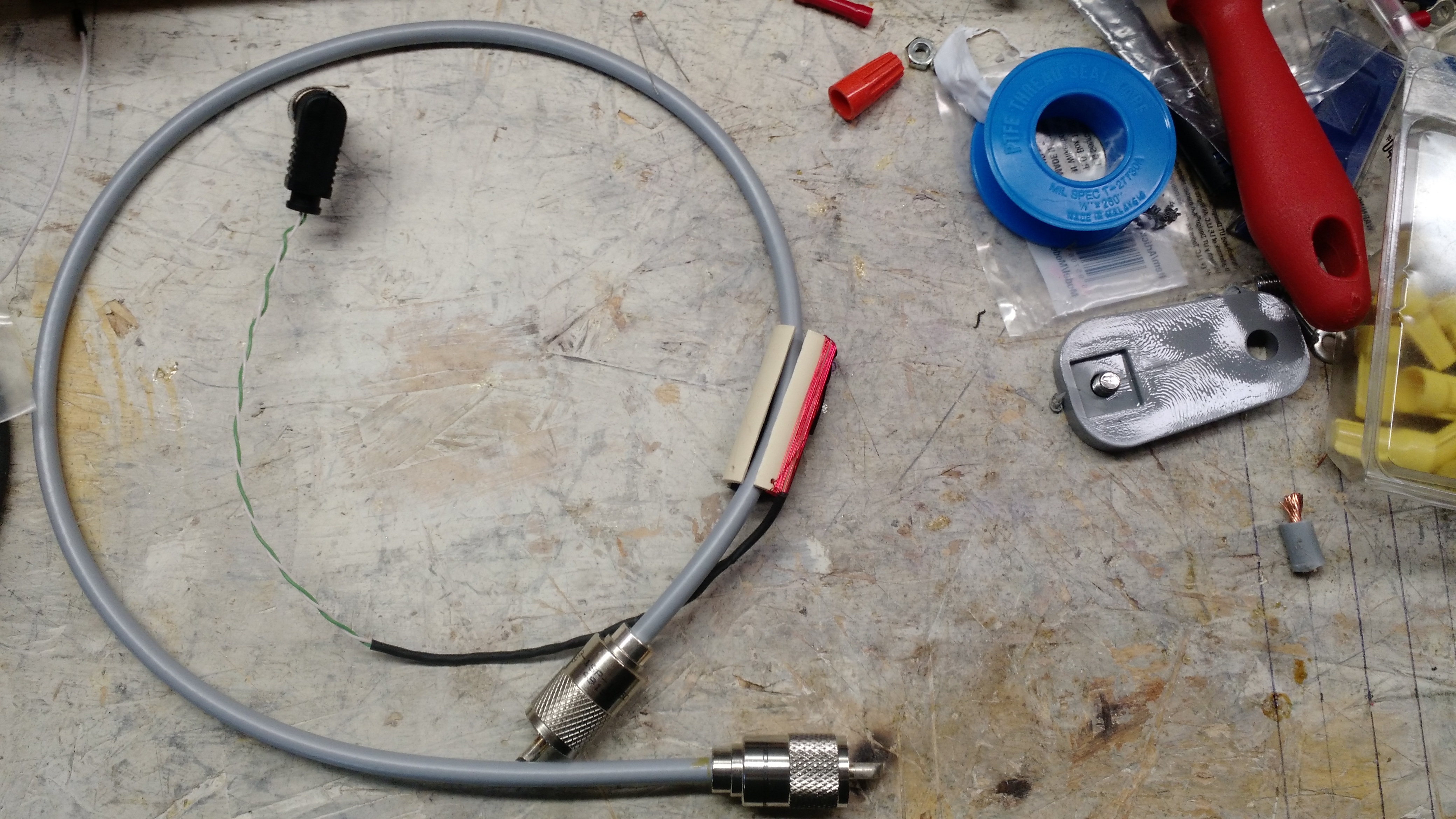
Inductive Coupler
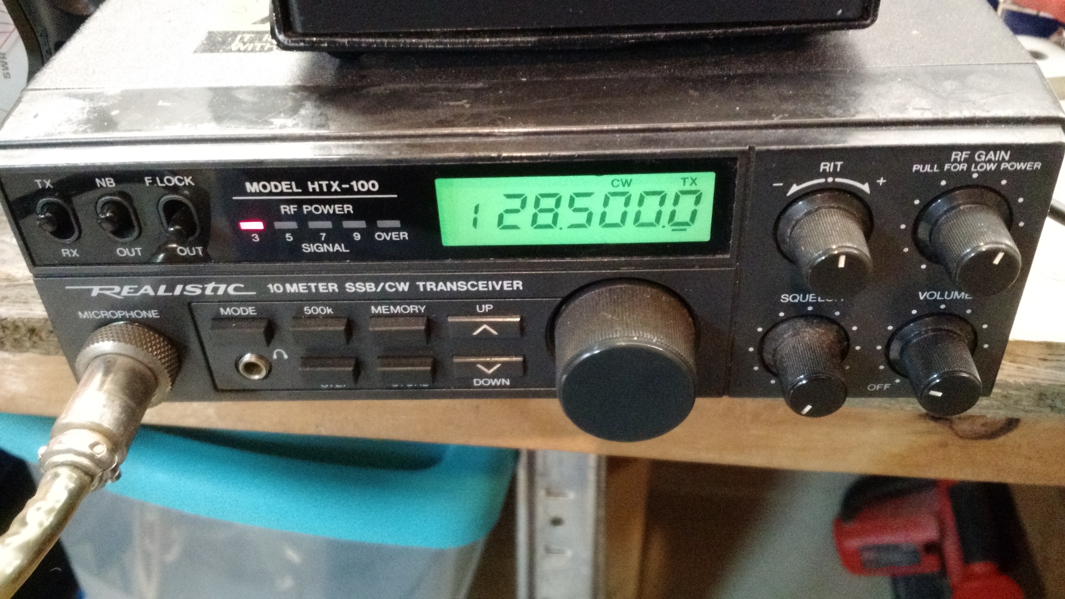
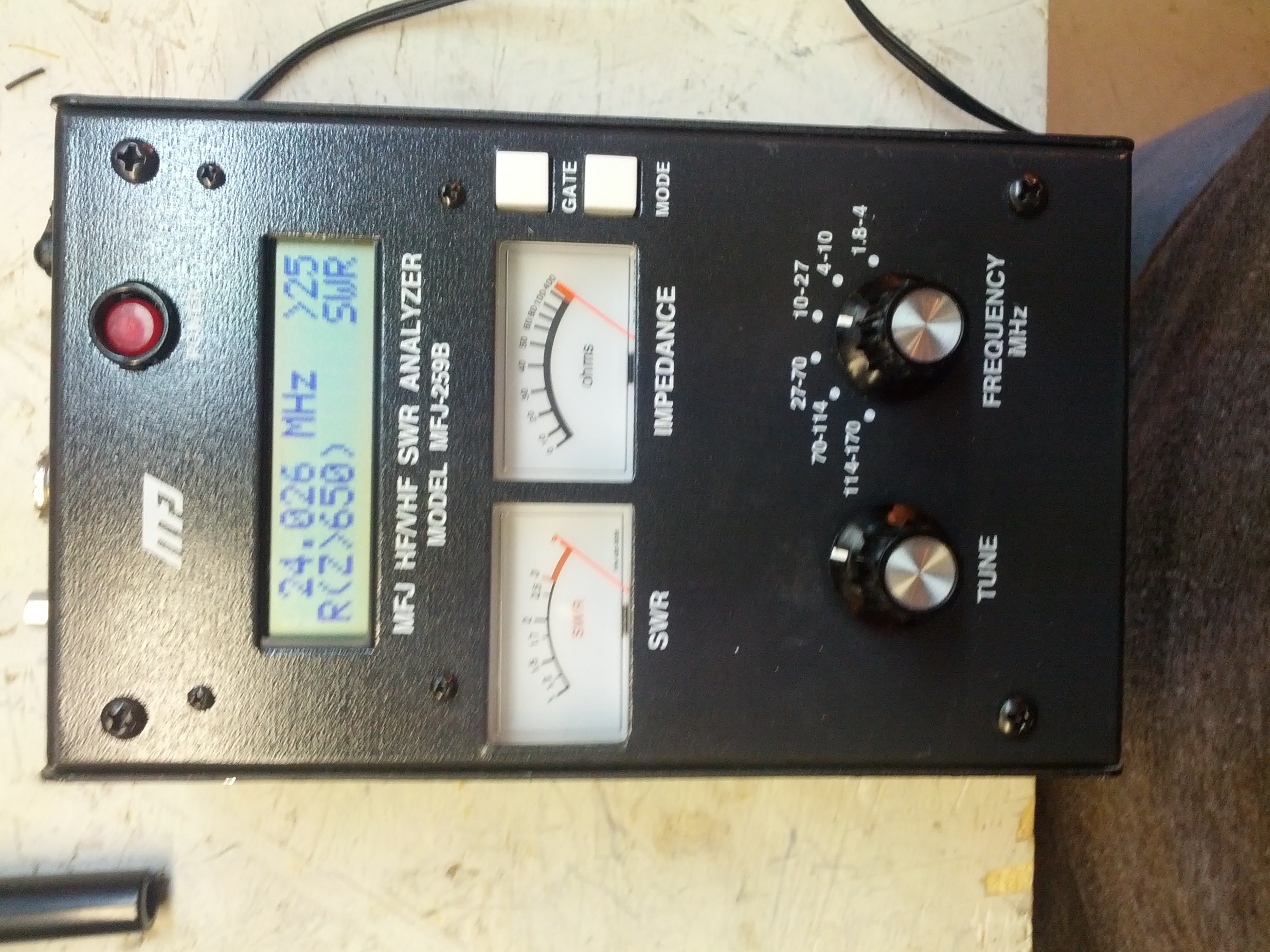
Radio set frequency (28.5 MHz)
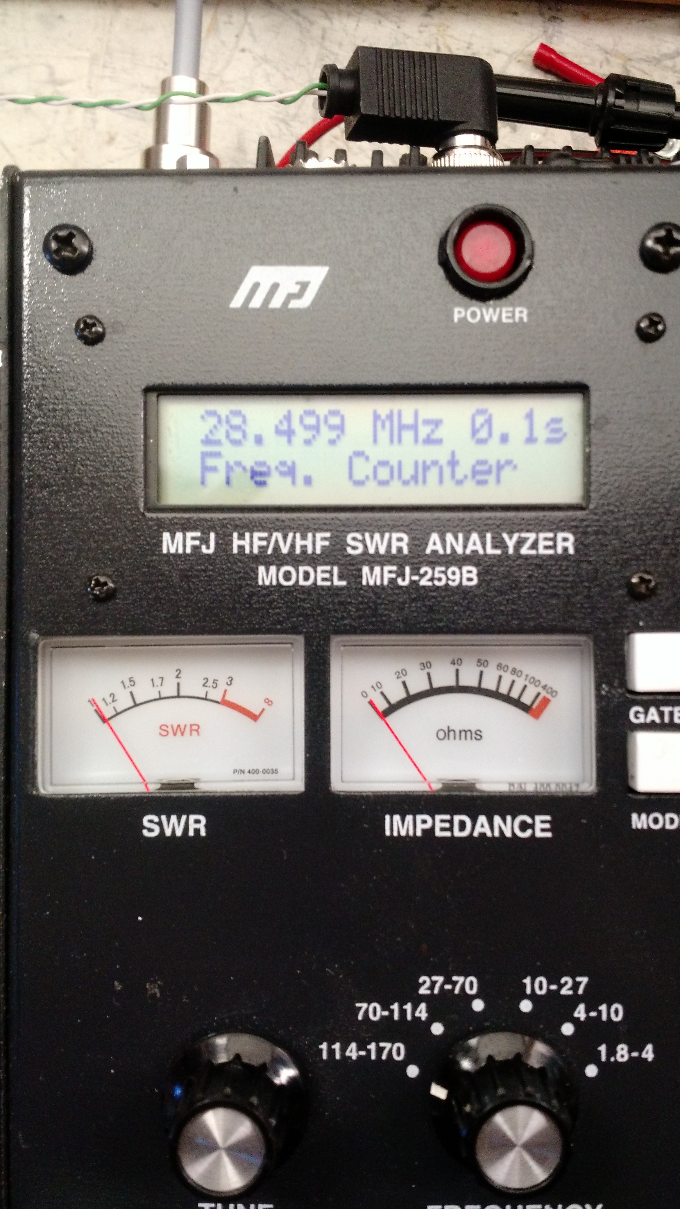
Frequncy (28.499 MHz, or close enough considering the potential error in the antenna analyzer)
-73-
Since I had a few minutes after the XYL went to bad (after a *very* busy Saturday for both of us), I went into the basement and played with the antenna analyzer.
This isn’t the most ground-breaking post on my blog, but they don’t really teach much about antenna analysis in traffic engineering classes!
Scop’d
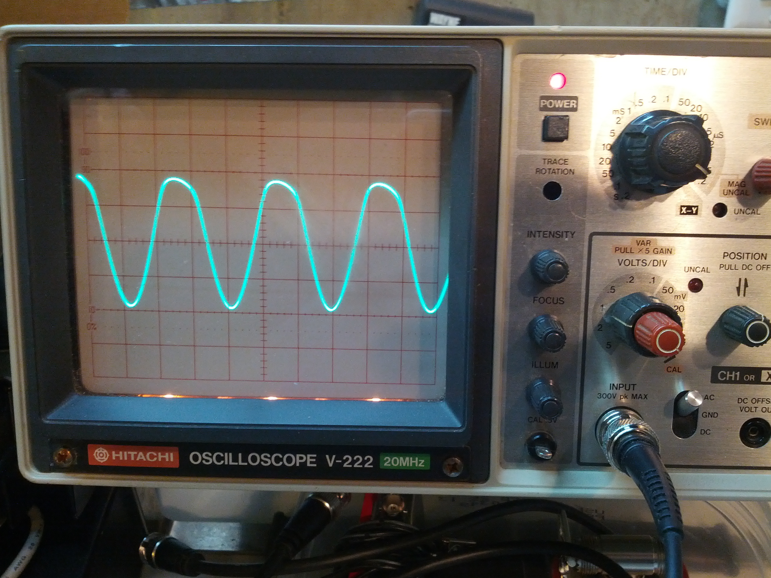
The first thing I did was drop the frequency of the analyzer to something low and see how much power the analyzer puts out. 4V peak-peak.
SWR Check – 25 Ohms
SWR is based on the mismatch between the impedance of the source and the load. So a 2:1 SWR could mean that the load is twice or half the source impedance. So I decided to put a few resistor arrangements on the analyzer and see if what happens is what I thought would happen.
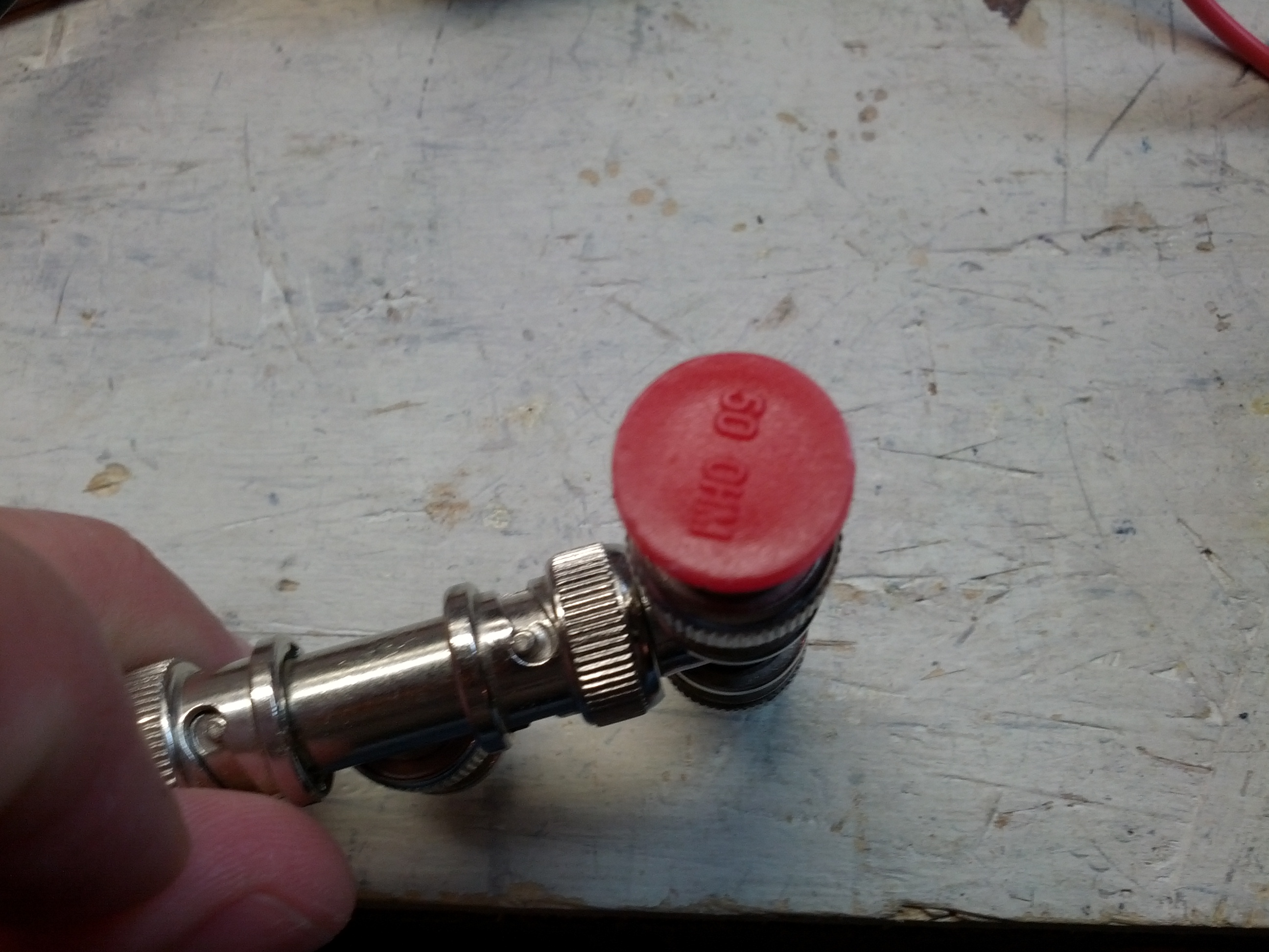
So I had these terminators from way back when they used BNC token ring networks. I’ve never worked with anything but Ethernet (using RJ-45 connectors), so I’m not sure how I got these, but they came in handy for this.
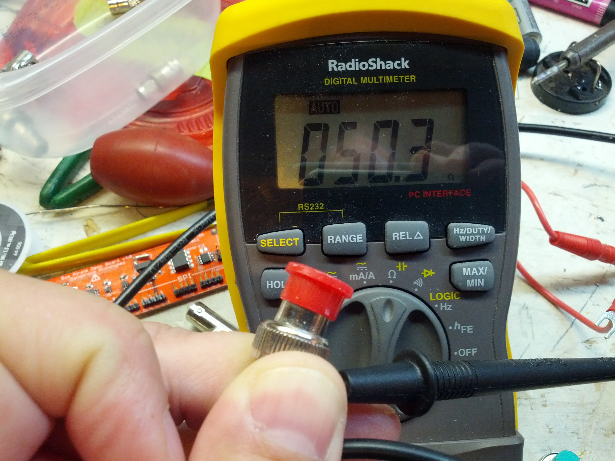
This one is 50.3 ohms. Within a 1% tolerance.
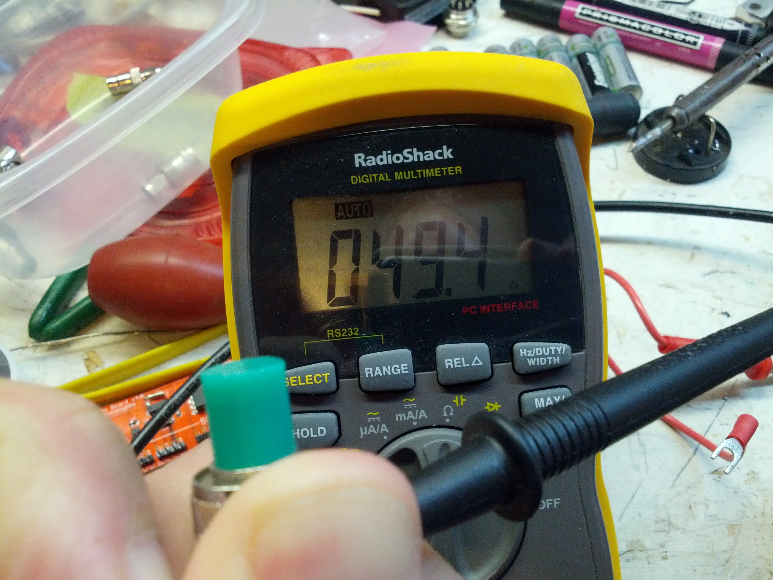
This other one is 49.4 ohms. Just around 1% off. For what I’m doing, close enough.
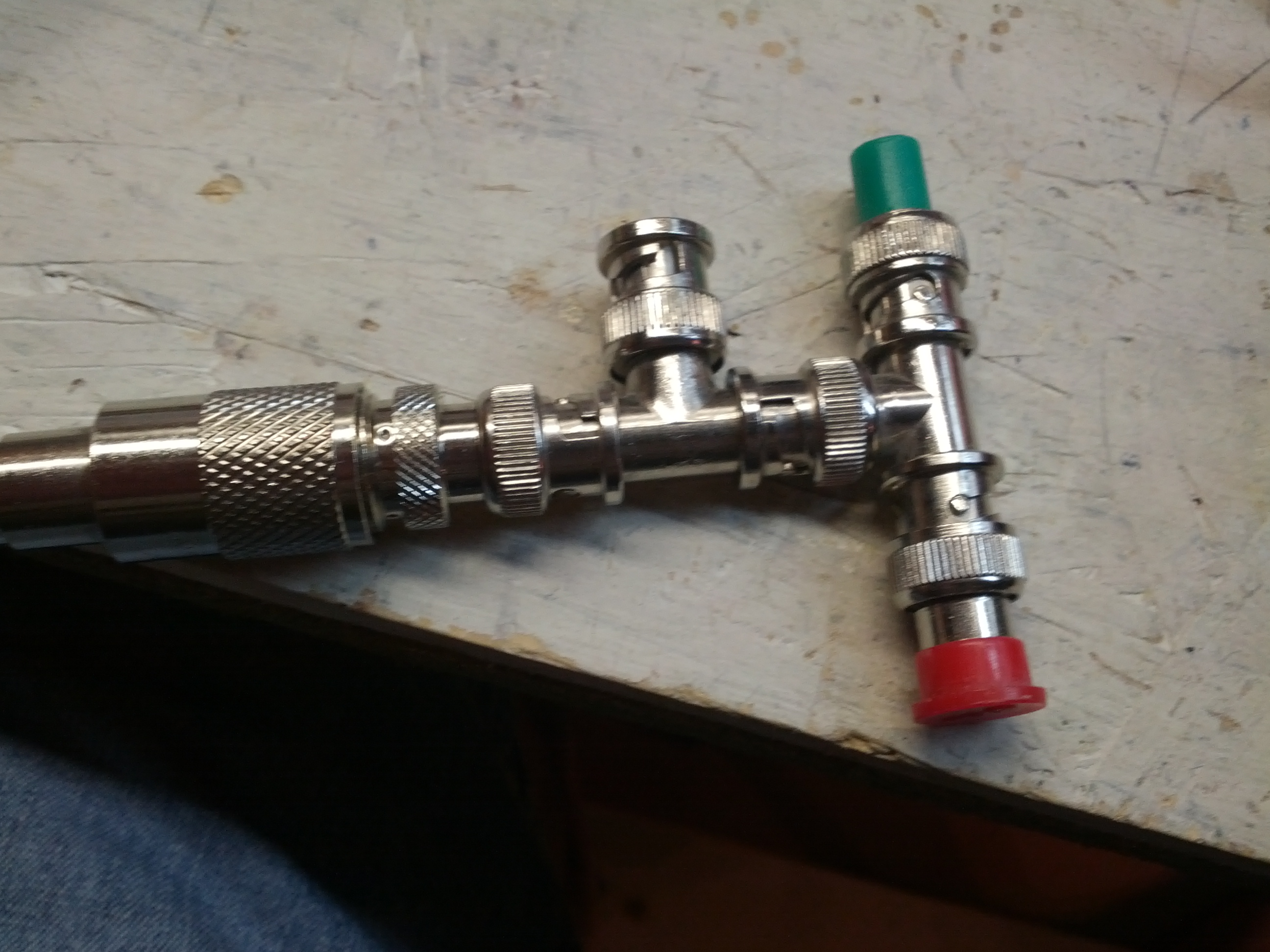
This was my redneck arrangement. This basically put the two 50 ohm terminator resistors in parallel.
This doesn’t quite have the resistance I was expecting, but the SWR is correct. Of course, there’s all sorts of stuff going on with the open end, the many connectors, and the 4 foot piece of RG-58. Given the fact that I had two 50 ohm resistors in parallel, I think I should be seeing 25 ohms R and (ideally) 0 ohms X.
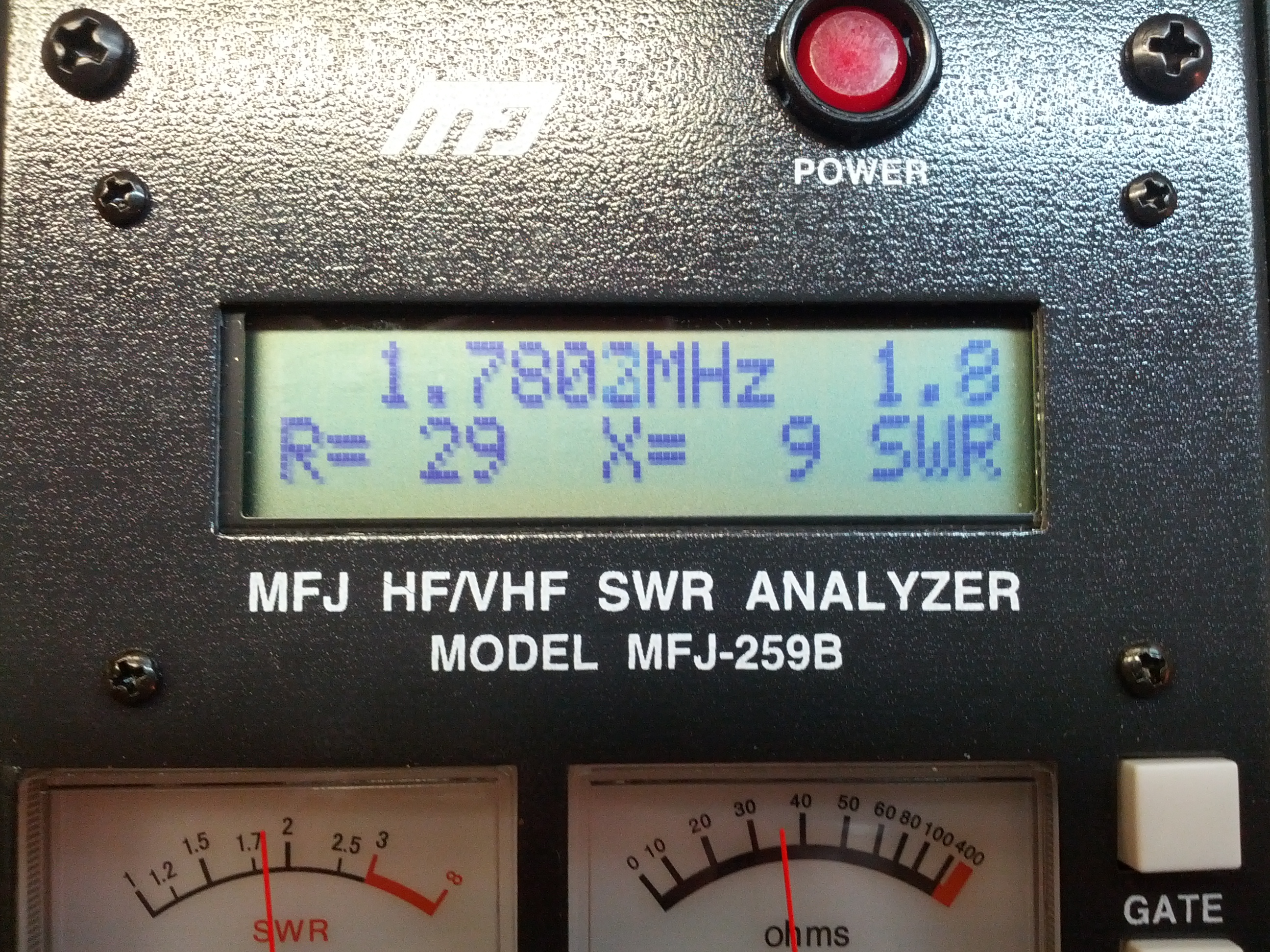
This seems a little more like it. Still a nearly 2:1 SWR and close to 25 ohms R, with very little reactive ohms.
SWR Check – 100 Ohms
Since I couldn’t figure out a way to make my two BNC terminators in series, I pulled a resistor out of my parts bin. It was really a 98.3 ohm resistor, according to my non-lab-grade Radio Shack meter, so I figure that’s close enough!
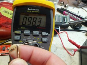
Close enough to 100 ohms.

This is how I did it.
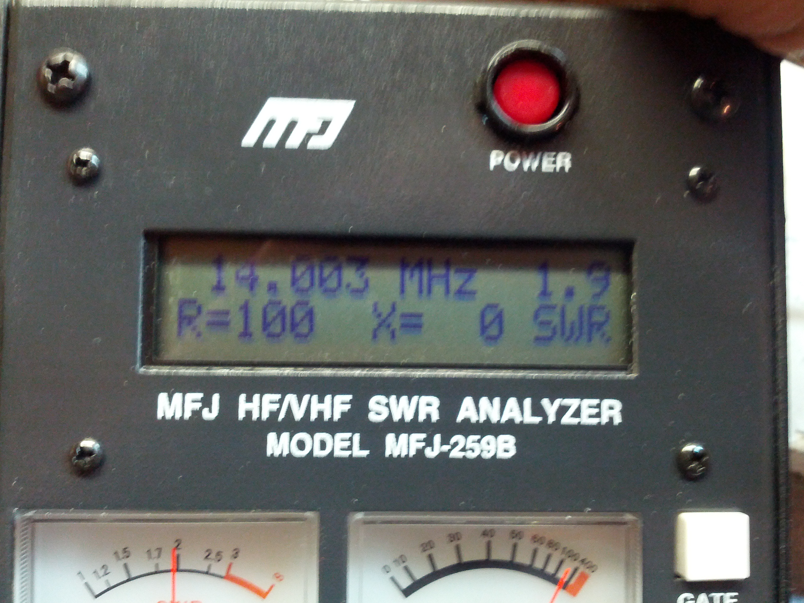
Hey look, exactly as expected. 100 ohms resistive, and 0 ohms reactive.
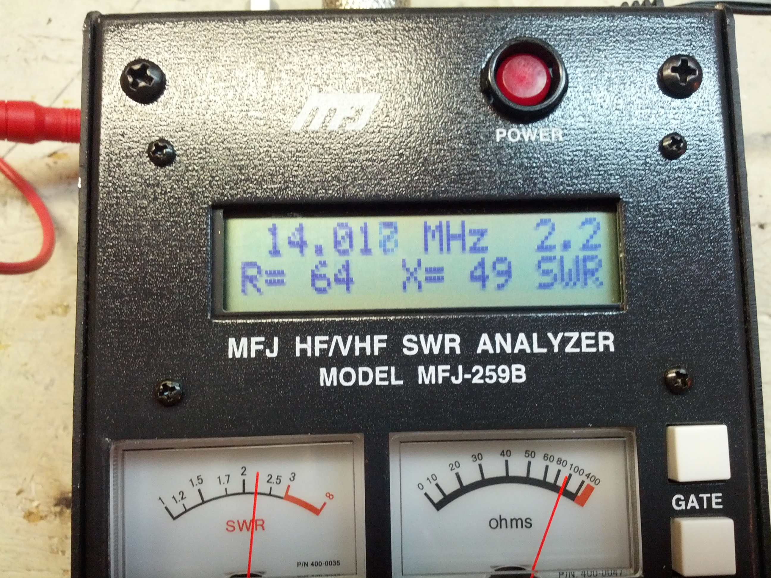
Other Dummy Load Test
I had a dummy load I built for QRP uses (specifically the Softrock). I built it a while back, which is why the callsign is wrong.
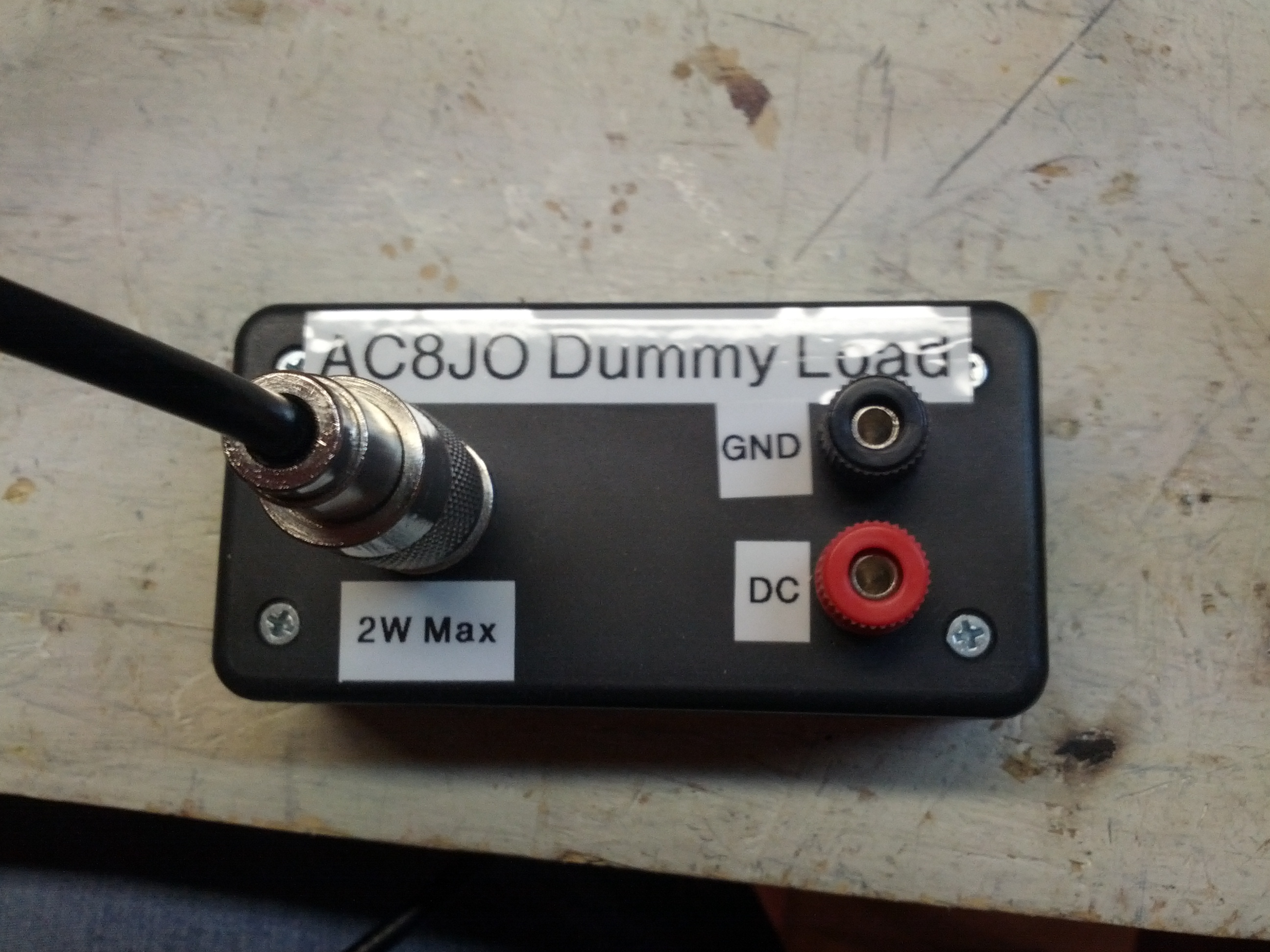
Just pretend it says “KE8P Dummy Load” 🙂

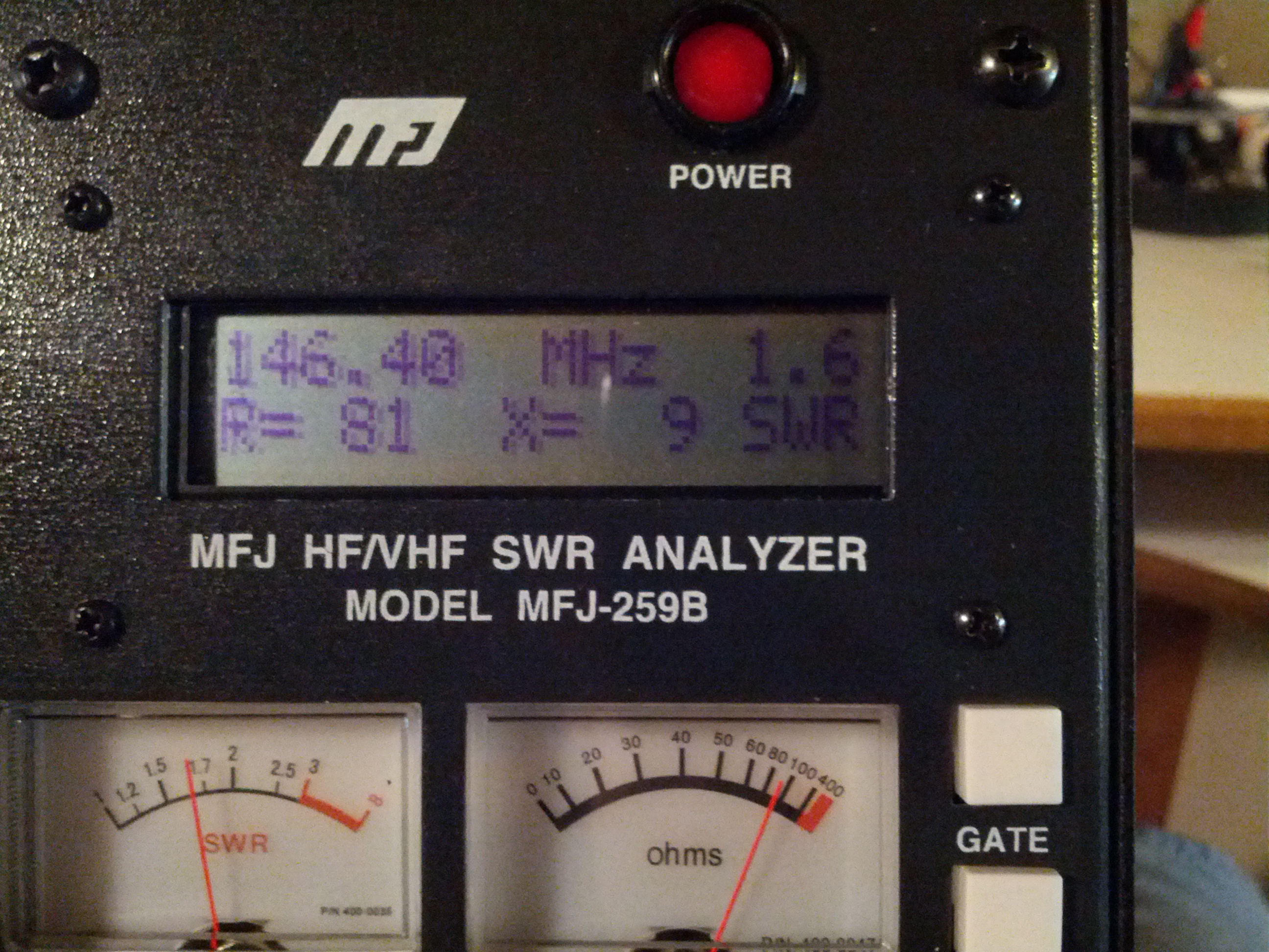
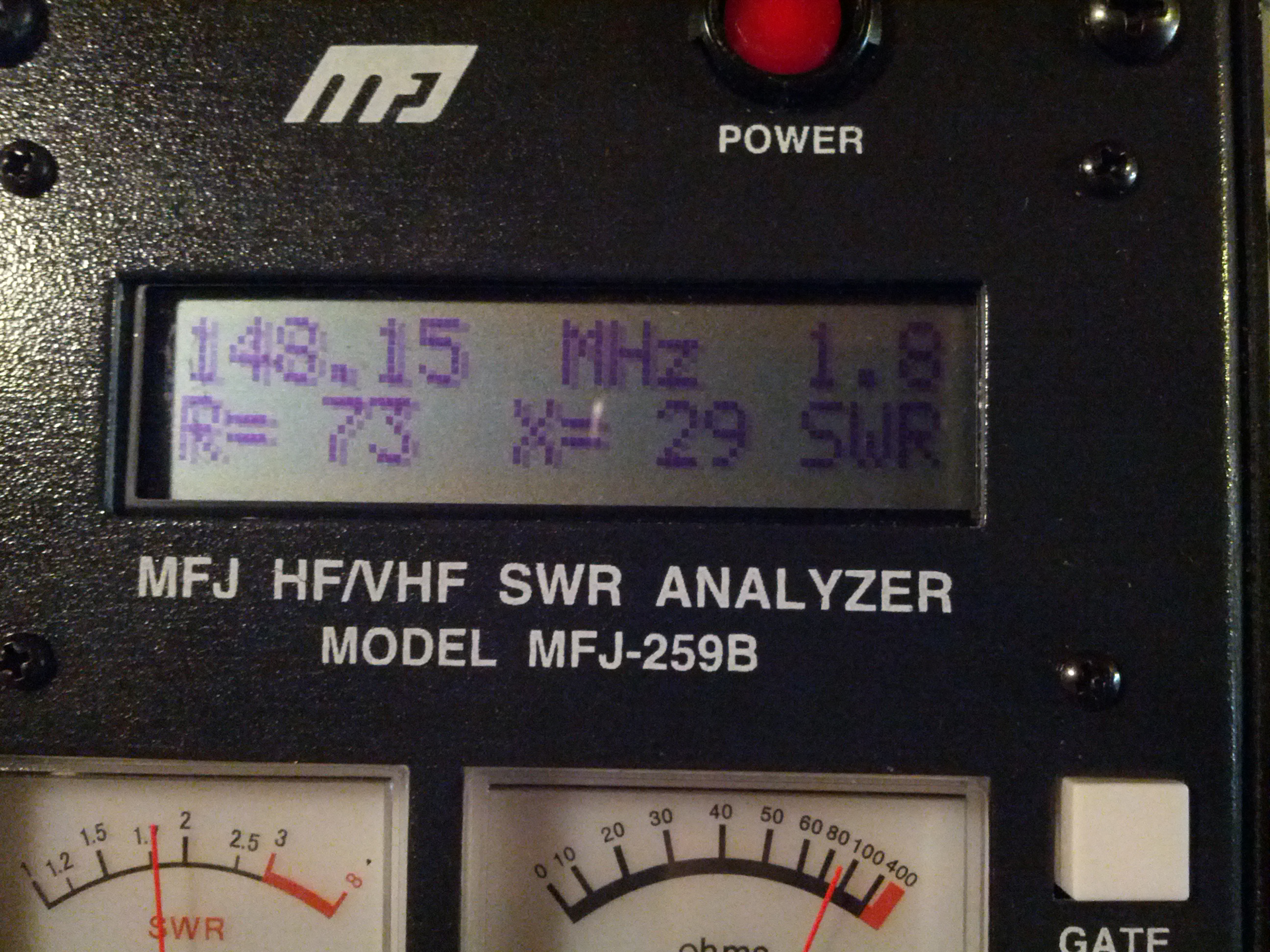
70 and 4? SEVENTY AND FOUR? WTF, it should be 50 and 0!!! I’ll just blame the extra resistance and all the reactance on the cable…
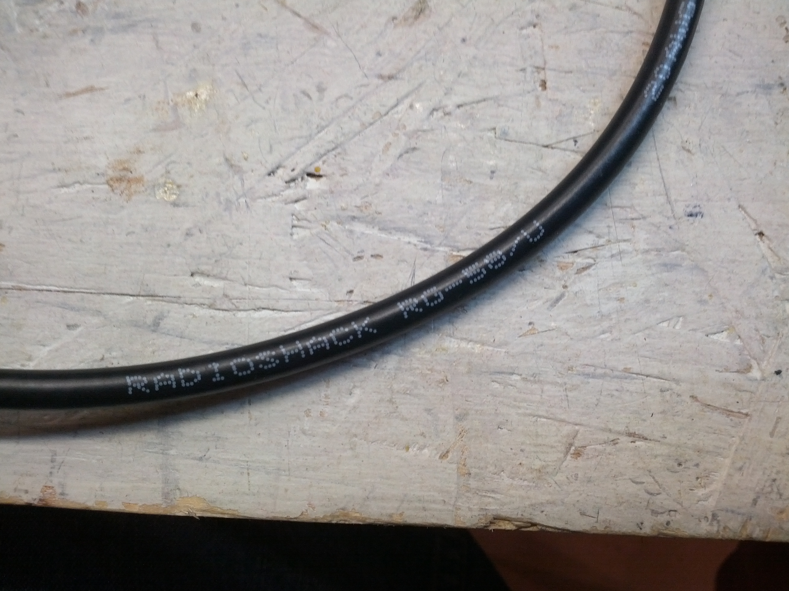
Maybe this is why it isn’t perfect. My coax isn’t exactly Belden or Times.
Capacitance Checks
So the MFJ-259B has a capacitance check on it. This is really for the capacitance of an antenna, not for what I did in the pictures below. I basically took a ceramic disk capacitor and clipped one end to the ground and the other I held into the center conductor of the antenna port. This is a 10,000 pF capacitor.
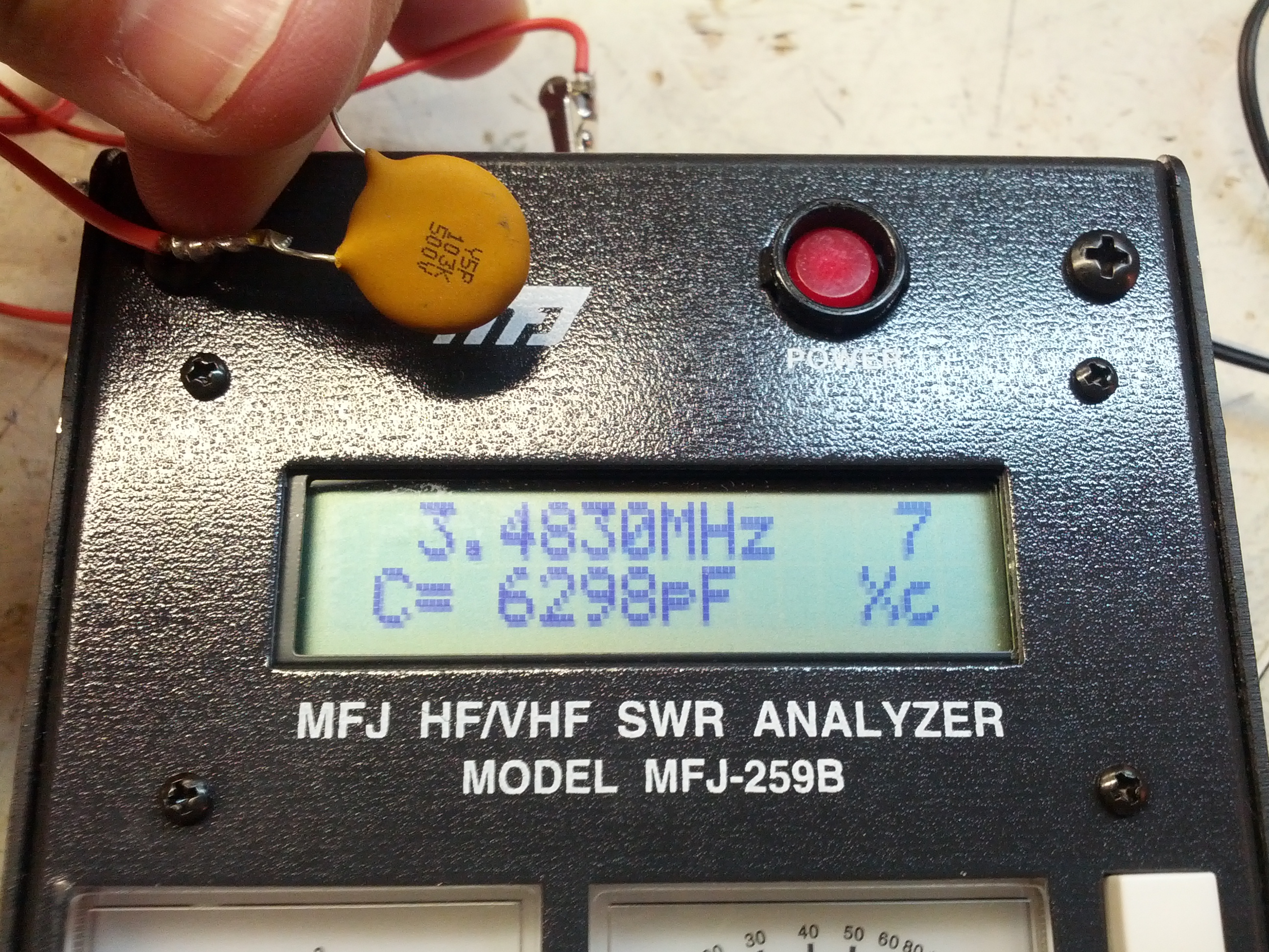
On 80m, this capacitor has 6,298 pf.
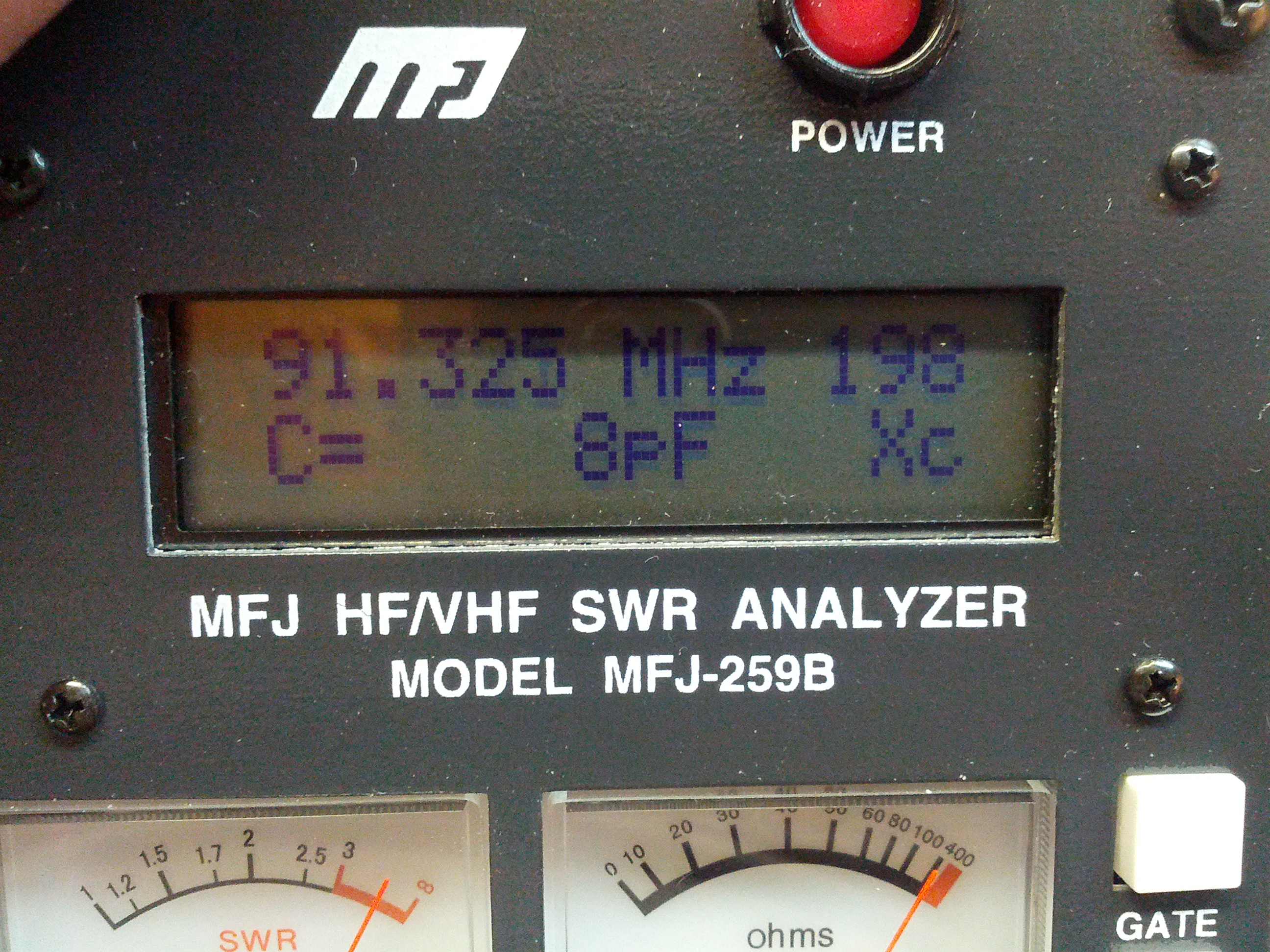
Up at 91 MHz, there’s only 8 pF of capacitance.
I figured the stuff above was a little more fun than me talking about how I tested every antenna I own… again.
-73-
Oh crap, that probably sounds bad. Ah well.
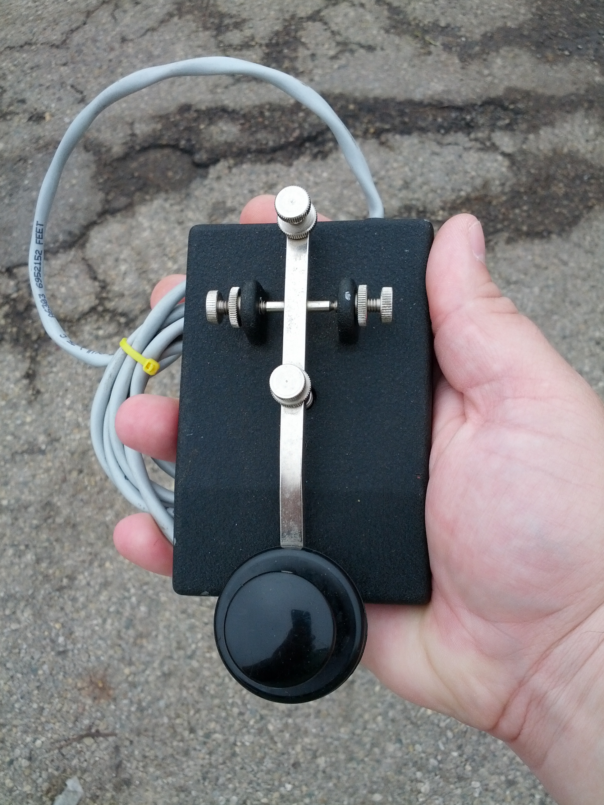
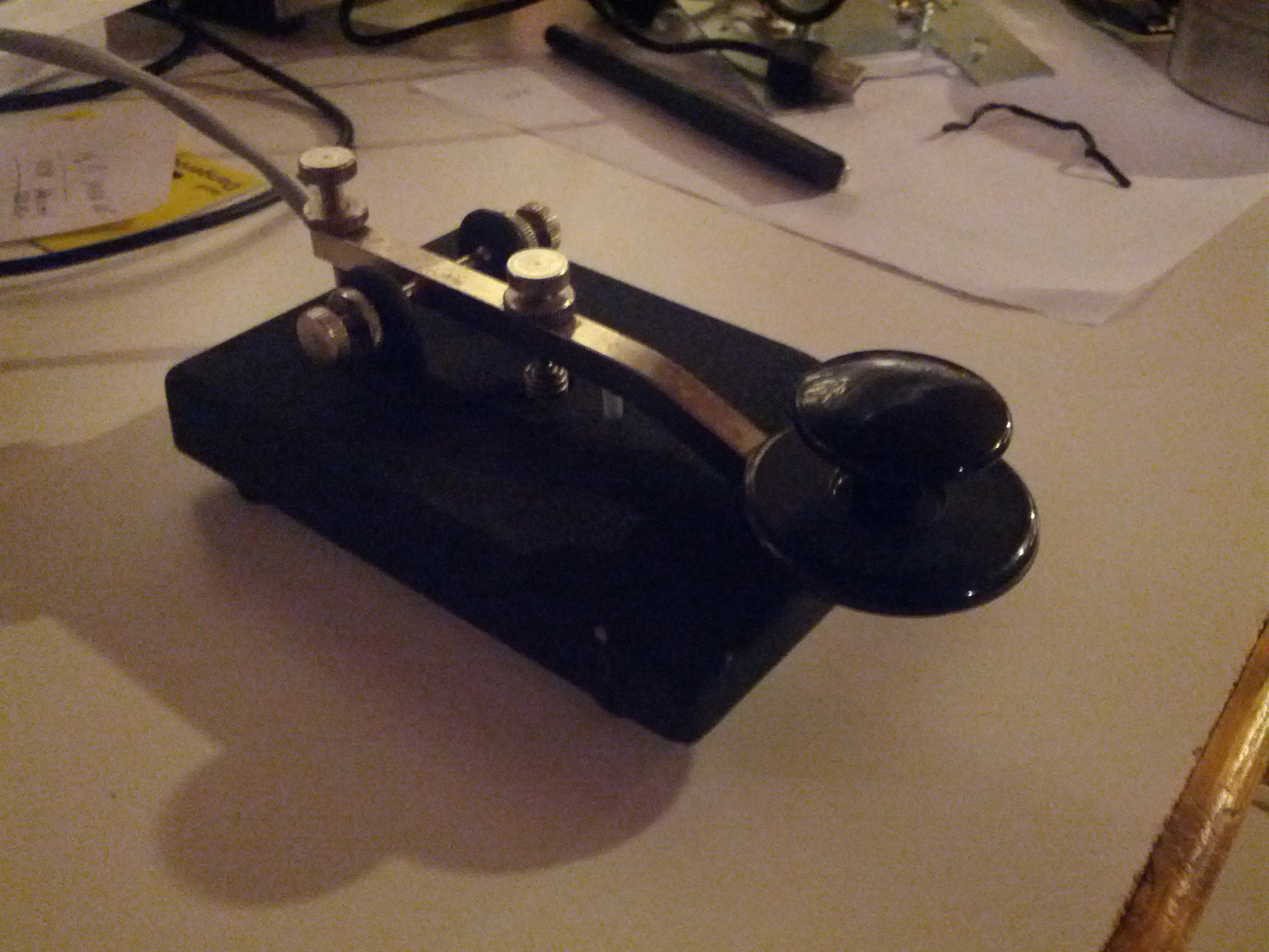
So my first find was a key. It’s nice, heavy, and probably has a history, which I added “purchased for $35 by KE8P” to.
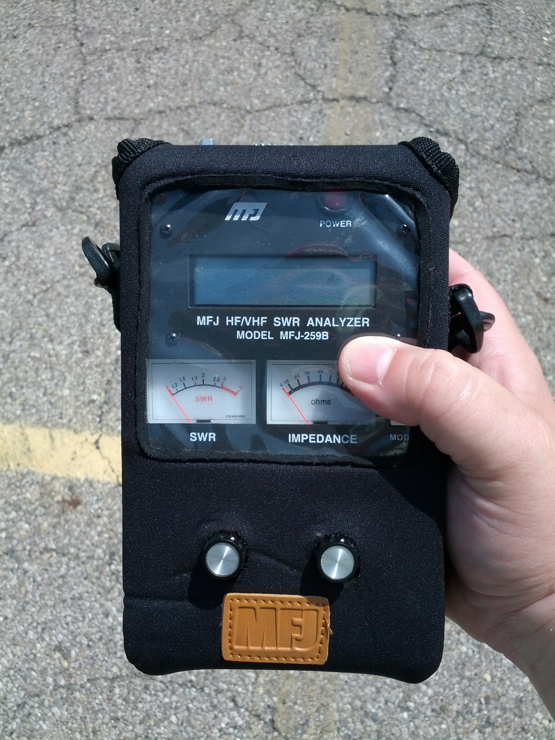
I found this. For $165. Like any normal ham that likes to push buttons and turn knobs, I turned it on, just to be greeted with it flashing “LOW VOLTAGE 6.5V”. I figured that was a sign that it probably works.
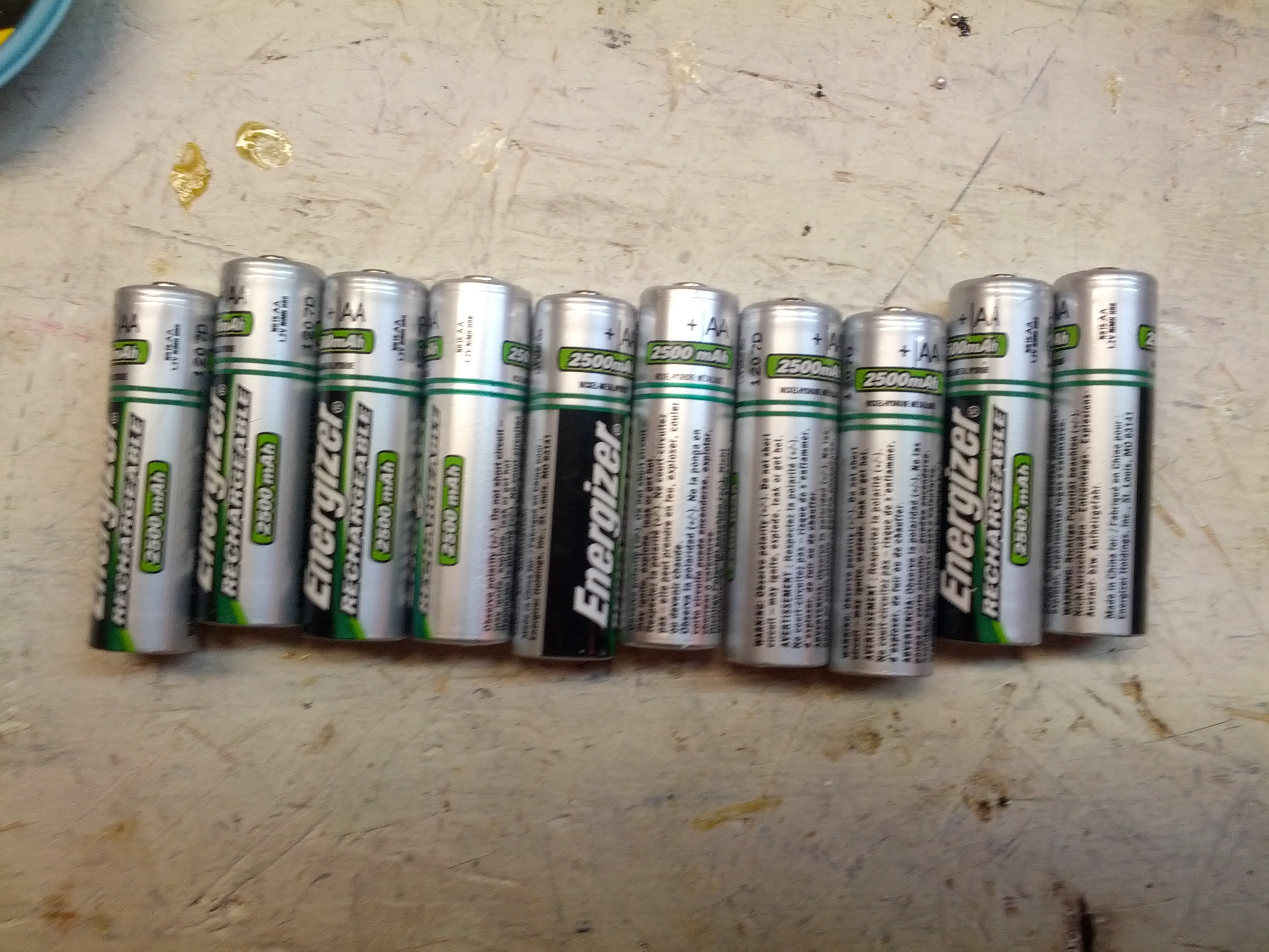
And when I got it home, I found these in it. Ten Energizer rechargeable batteries.
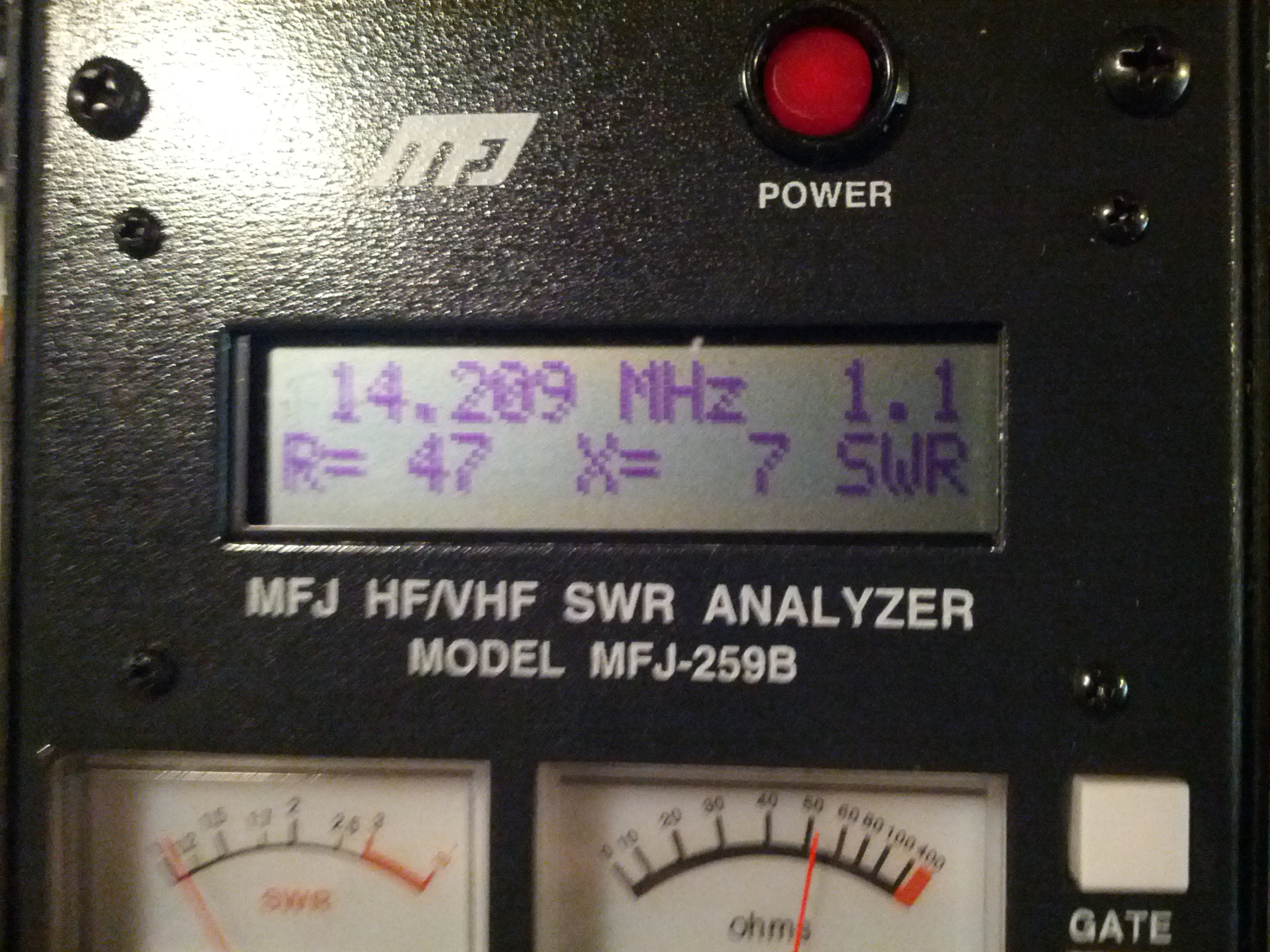
So I removed the batteries and plugged in a wall wart. I was greeted with “VOLTAGE OK 15V” and something like the display in the picture above. I did check my dummy load, it claims it is around 50 ohms at 1-1.3 SWR. Guess it works!
Also included were these. They are coils to use the analyzer as a dip meter. I didn’t really need these, as I built one (they’re really quite simple). My built version worked quite well for the coax traps on my attic trap dipole.
So I did try it with my HF and 2m antennas…
Not bad for the severe destruction of 5 clothes hangars
My HF antenna isn’t too bad on 2m…
…and it does okay on 20 meters, too…
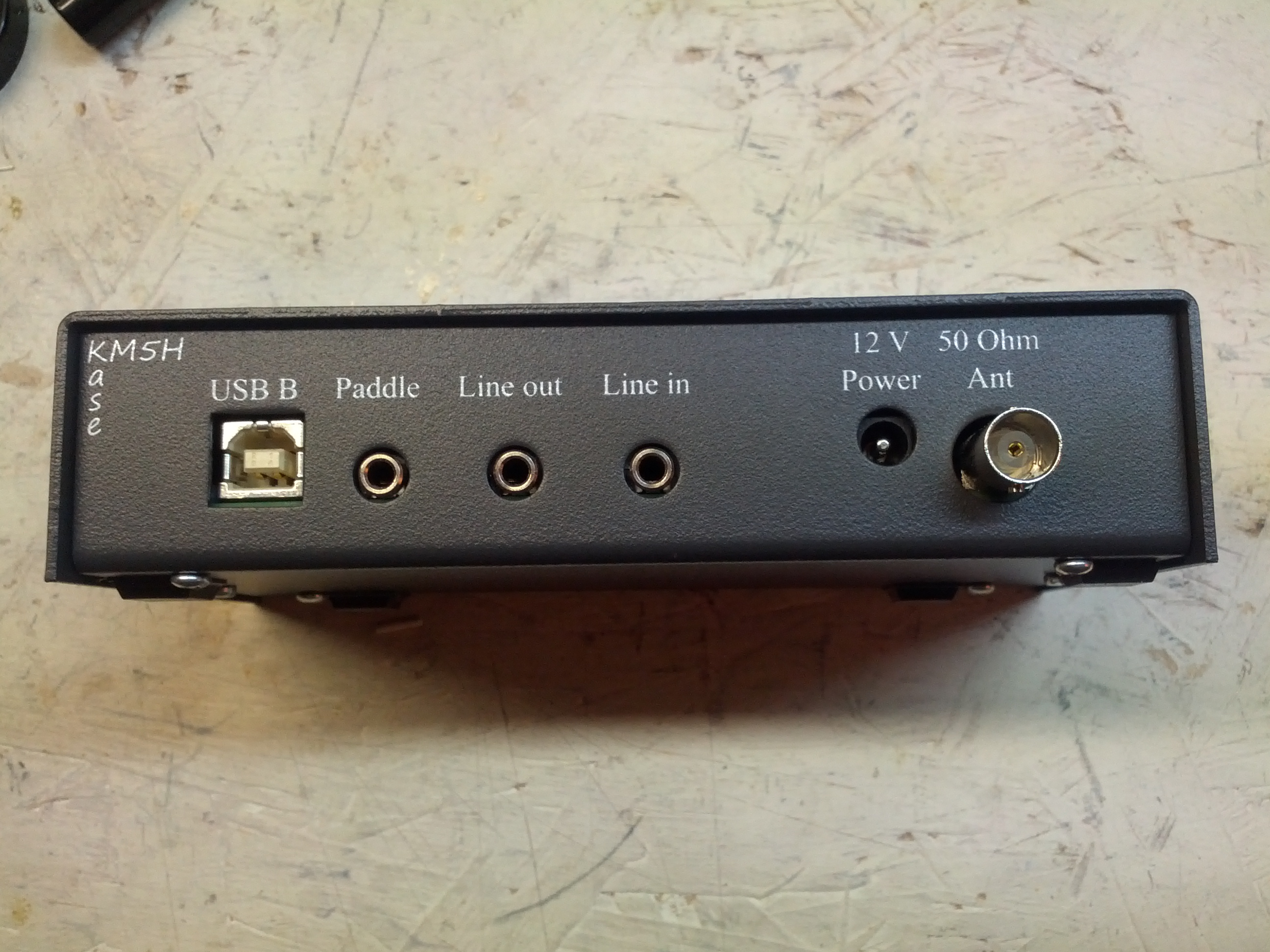
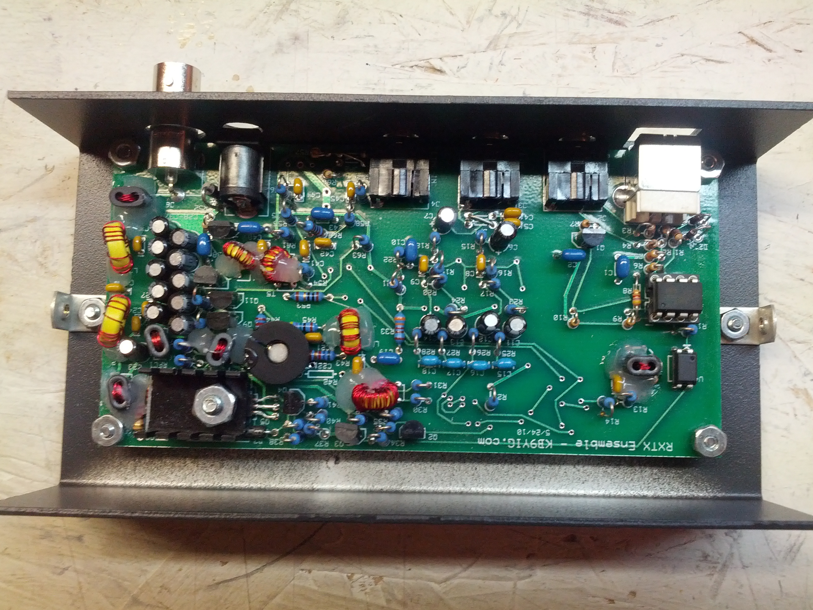
The third purchase was a case for my SoftRock
The last thing I got was some fiberglass mast. I didn’t take a picture of that.