Tag Archives: ten tec
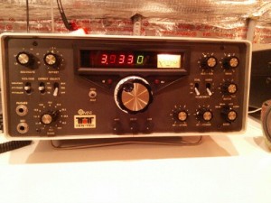
Since I fixed my Ten Tec Omni, I’ve used it a little and I’ve had one major complaint: it doesn’t talk to the computer. In fact, in the CQWW contest, I mistakenly logged my first contact on both the incorrect band and the incorrect mode (I was operating SSB on 10m, and it was logged as CW on 160m… never mind that I have never operated 160m CW!).
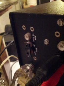
When I first got it, I started looking at the different inputs and outputs on the back. One is very curious: the VFO in-out, which is shorted together.
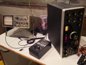
So I decided to look into what these jacks do. Enter the oscilloscope to check the voltage coming out of there (so I don’t blow my antenna analyzer).
After checking to insure that there isn’t more than 2 volts peak-peak coming from this (there’s actually about 0.5 volts peak-peak. Once I was sure that it was safe for the antenna analyzer, I took the oscilloscope probe and plugged it into the analyzer to see what frequency that jack used.
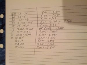
I was surprised a little to see that the VFO output for setting the radio at 10 MHz was 5.01 MHz. Then, I started tuning around and seeing a little pattern, which can be seen in the image below:
So each of these tells me basically the offset (within 0.01 MHz)
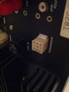
In order to get the actual frequency to a computer, I need to do two things: build a frequency counter that I can plug into something that sends a serial string to a computer, and get the band that the radio is switched to, which would probably come from this jack:
Sometime in the future (whenever I get back into working on this), I’ll see if I have the connector for that accessory jack and set up something to read it.
-73-
The finals are replaced and tested! 110 watts out!
So I started looking over things. One thing I’ve been looking into is the zero beat. It seems to me that when you push the button, it should emit the CW tone. I can get it to emit the tone, but only after pressing the zero beat button many times.
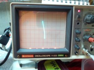
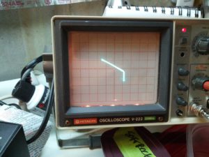
I also don’t like the CW tone. It seems odd even when at the correct frequency. I hooked up the audio output to my oscilloscope and saw the audio output… It looks…er…interesting.
I think I was expecting to see more of a sine wave as opposed to a sawtooth (I guess) wave.
There is one minor little problem – it appears the antenna isn’t properly connected to the receive part of the circuit, because it can’t hear anything. It does transmit on the correct frequency (per my antenna analyzer), so the problem is likely minor as opposed to something going bad related to the frequency or mixer.
This still feels like yesterday’s repair, even though it was tonight when I did all this.
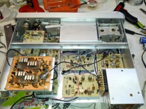
Since I had the final module out from yesterday, I hooked power to it to test. I first tried the driver, and it didn’t trip the circuit breaker. Then I tried the high power amp and it tripped the circuit breaker immediately. Fearing the worst, I embarked on the long process of removing the finals (which was not fun because of how they were stuffed in there.
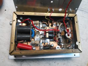
Finals in their copper case. Getting the heatsink off wasn’t too difficult, but getting the circuit board out of the copper was a pain.
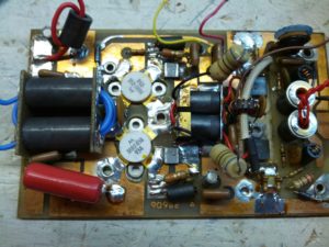
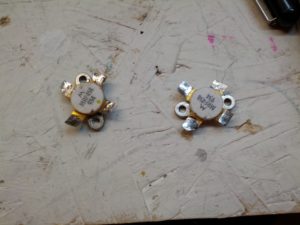
After a lot of work with a heatgun and soldering iron and wick and a bulb, I got this out.
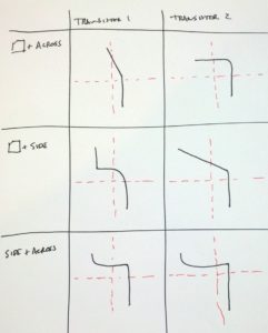
So after removing these, I put them on an octopus tester, and tested them. The results are interesting. It also says that one or both of them is likely bad. These things aren’t cheap, but with how much of a pain it is to remove them, the smart thing would be to replace both, since one went, the other is likely not far behind.
Note: the upper-left and middle-right are nowhere near the same:
Next up: replacing the transistors and powering the unit back on!
-73-
For those that do know me in real life, I’m not an electrical engineer, I’m a traffic engineer (more specifically, I do traffic forecasting, which also makes me somewhat of a programmer and a transportation planner). I can build electrical things when they’re easy or when there’s a schematic.
For those that have been following this blog, I just put my only real* HF rig in my truck.
For those of you that have been following me on Twitter and have a damn good memory, you may remember my first rig was a Ten Tec Omni.
So enter my issue. I have a broken (but otherwise great) rig at home, I’m too cheap to send it to Ten Tec**, and I want to learn more about repairing my equipment. This is a lot harder than Arduinos and Raspberry Pis and Beagle Bones!
The Transceiver
The transceiver is a Ten Tec Omni C Model 546. It has all the options – three crystal filters (2.4 KHz, 1.8 KHz, and 500 Hz) and three audio filters (10 KHz, 500 Hz, and 150 Hz of audio) PLUS the WARC band (12 meter and 17 meter) crystals installed.
The guts of the rig are modules – each plugs into the chassis.
The Problem
While running around 25 watts out on the NAQP RTTY contest a few years ago, the rig and power supply died mid-transmission. I tried throwing the switch off then on, and the I saw the lights (the meter and the frequency display) light up and immediately die.
I tested the power supply, and it has 13.8 volts out.
I put an ohmmeter on the rig’s power connectors and saw very low ohms (something like 200 ohms). Seems to me that a part failed and opened a path to ground. With that thought in mind, I did check the 1 uF capacitor and the diode that connect between the +V in and ground (those seemed like the easy tests. I basically disconnected both from ground and tested the resistance betweren +V and GND and there was no change in resistance. However, the rig is modular, and there are dozens of places where there is a capacitor between a +V and GND connection.
My Thoughts
One thing about this rig is that everything is modular. I can remove parts very easily and test the resistance to ground (which I’m guessing should be very high). So if I find something that has a low resistance to ground (in the ohms instead of kilo-ohms), I should probably start looking there.
One thing I did do is remove the meter light bulb and the resistance went up to 450 ohms. It seems to me that the resistance should be somewhere in the 10 kilo-ohm range, but again, I’m not an electrical engineer.
Reader Participation
Let me know in the comments, via twitter, Google+, or email – am I on the right track? Anyone have one of these and know of a common failure? I’ll gather a work-week’s worth of comments and do tests on the weekend (or through the week, if I have the time).

