Tag Archives: usb
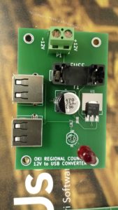
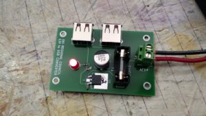
My work has taken me down the road of using Raspberry Pis as data collection devices. This means I need to power a Raspberry Pi in the field. I’ve had trouble finding a reasonably-priced 12V to 5V USB adapter that I could easily and safely fit into a box with a RPi. So I designed one in KiCAD and built it. The design is on my work github account.
I’m ultimately designing something that will connect to a battery, and batteries can explode if mistreated. Testing is critical, as is circuit protection (the fuse). I’m envisioning this to be in a box on the top of a pole with a camera, so the lead going from the battery (which will likely be on the ground) will be fused in case the wire gets cut. This is critical for the same reason it is necessary in a car – to protect the battery from short circuiting should something happen.
In putting these together at home, I tested these in every way I could think of, and assembly and testing went something like this:
- Solder SMD C2 and R1
- Test resistance from 7805 output to LED positive solder hole, should be 330 ohm (I used 330 ohm resistors instead of 310, since I don’t happen to have any 310 ohm).
- Test continuity from 7805 output to ground via connected to C2. Should show no continuity.
- Solder USB connectors and C1
- Test capacitance from 7805 input to to ground via near C1. Should show a reading (mine all showed around 1000 uF, which is high, but my understanding is that multimeters are notoriously bad at capacitance)
- Add input headers, fuse holder, and LED
- Test continuity between inputs – should immediately beep, and then drop to no continuity after capacitors charge
- Apply voltage, LED should light, all magic smoke should remain contained in devices
- Test voltage from 12V- to 7805 output – should be 5.0v (mine showed something like 5.007v)
The one thing I was unable to test was the actual USB output voltages, but it seems to me that they should be okay.
I have five blank PCBs left for additional builds should I need it, although I’d have to have work buy more components. Maybe I could get some larger 7805s that would fit the ground pad…
-73-
I decided to move all my radio stuff from my desktop to my laptop for now. My desktop has never been a reliable computer – there’s something wrong with it that causes it to stall (and whatever it is, it’s hardware and not OS, as it has done the same with XP or Mint). It also goes SLOOOOOOOOOOOW. In fact, it goes so slow, I tend to boot it at least 10 minutes before I need it, and it was degrading to the point where it wasn’t even ready then.
So, one thing I ~need~ want to be able to do is digital modes like RTTY (I know many hate it, but I do enjoy RTTY contests). The problem I ran into is not a new one: there’s no serial port on my laptop, meaning my old way of triggering my radio’s PTT is now a useless group of components.
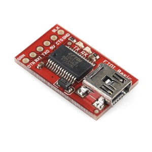
I happen to have a Sparkfun FTDI Breakout board sitting nearby. It has a damaged trace to the 5V output caused by the fact that my soldering iron is an old Radio Shack 45W pencil (which puts out far too much heat for many boards). I had set it aside with the intent to use a wire jumper to fix the problem, but after getting it back off the electronic triage shelf I realized that everything worked except the 5V output. The module looks like this (picture credit from Sparkfun):
I first wired it in with my transistor switch to look something like this:
It didn’t work.
I started to investigate. I noticed that DTR, RX1, TXO, and CTS were all 5V, but DTR would drop to 0V when the DTR was activated via software.
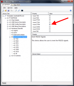
So I did a little research. FTDI makes their boards customizable, so I looked into the software from FTDI’s website and found a configuration utility called FT_PROG. From this utility, I was able to read the chip and then re-write the chip to invert the DTR signal. Note the screenshot below:
This allows me to use the FTDI board with an optoisolator and trigger the PTT. The schematic is below:
So now I just have to fix the USB soundcard issue…
-73-


